@EU,
pcbs arrived in Berlin.")

My plan for monday evening is to do the packaging of the boards, tuesday / wednesday (latest) starts shipping ... I thing it will be a "christmas gift" (I'm this weekend out of Berlin).
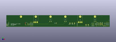
An other offer for you guys is that I had some power supply boards (FW style) left (sorry the picture is a little distorted, please click on it) => 10€ / each

And from the F3 GB are some Bridge Boards (rectifier) left => 1,50€ / each

For these Bothe extra boards:
- First comes first serve
- Payment must be done latest until Monday 10:00 o'clock.
So, please let me know, thanks for trust me!
pcbs arrived in Berlin.
My plan for monday evening is to do the packaging of the boards, tuesday / wednesday (latest) starts shipping ... I thing it will be a "christmas gift" (I'm this weekend out of Berlin).
An other offer for you guys is that I had some power supply boards (FW style) left (sorry the picture is a little distorted, please click on it) => 10€ / each
And from the F3 GB are some Bridge Boards (rectifier) left => 1,50€ / each
For these Bothe extra boards:
- First comes first serve
- Payment must be done latest until Monday 10:00 o'clock.
So, please let me know, thanks for trust me!
Can you ship these boards to US? or it is Euro only.
thx
al
thx
al
@EU,
...
An other offer for you guys is that I had some power supply boards (FW style) left (sorry the picture is a little distorted, please click on it) => 10€ / each
An externally hosted image should be here but it was not working when we last tested it.
And from the F3 GB are some Bridge Boards (rectifier) left => 1,50€ / each
An externally hosted image should be here but it was not working when we last tested it.
For these Bothe extra boards:
- First comes first serve
- Payment must be done latest until Monday 10:00 o'clock.
So, please let me know, thanks for trust me!
@hifibluedevil,
will write you later a PM.
Thank you Carsten.
Any chance on having another group buy?
I'd say odds are good if you're volunteering.
(Source files in post #205.)
Cheers,
Jeff.
You have it correct. (Note the little "wing" on the silkscreen drawing which sticks out at that point. That's the pin-1 indication.)
I noticed in your picture in the main J2 thread that the right-angle heatsink was very close to the resistor leads. Any chance one of them was shorted by the right-angle piece?
If not, post more pictures and we'll see if we can spot anything....
I noticed in your picture in the main J2 thread that the right-angle heatsink was very close to the resistor leads. Any chance one of them was shorted by the right-angle piece?
If not, post more pictures and we'll see if we can spot anything....
You have it correct. (Note the little "wing" on the silkscreen drawing which sticks out at that point. That's the pin-1 indication.)
I noticed in your picture in the main J2 thread that the right-angle heatsink was very close to the resistor leads. Any chance one of them was shorted by the right-angle piece?
If not, post more pictures and we'll see if we can spot anything....
IU was going to move it to the other thread, but will post back here since you beat me to the move: Here is what Jeff was replying too//Okay guys, plugged in left side board and the mains bulb tester lit-up full on and stayed there. Power supply checks out at 25v. I know if it draws enough the bulb can lite, but I wasn't sure, so I immediately powered down and pulled the board for inspection. Checked all solders and they look good no bridges or cold. Went through all the resister values per Jeff's print and all are okay. Caps are right value and polarity is fine. The only question mark is the 4N35 orientation.
I have marked pin 1 with the dot on the chip and how I have it in the circuit.
Attachments
@ Jeff
They are close for sure, but I inspected all for clearance before putting power to it.
I also checked the bulb in the tester and it is one of those new deals that gives off equivalent of 100W, but in reality, it is draws on 53W. How much does the circuit draw, could it just be that the circuit is drawing more than the 53W? DId I read somewhere that you had 60W at idle?
Last edited:
- Home
- Group Buys
- GB "long and skinny" FirstWatt J2 clone PCBs