If there is no Dc across the current sense, perhaps it is AC coupled? The Aleph topology has a current sense resistor and is what allows the active CCS to react quickly and increase the damping factor. If you can send me a link to the actual schematic of the F7 clone that would be helpful. My guess is that the SSR protection circuit will work fine.
No - not AC coupled. But no DC offset for sure (it gets adjusted to zero). If there is appreciable DC at the speaker hot terminal, something has failed.
I think the SSR will simply see the combination of the speaker and sense resistor as a combined load (speaker impedance + .3 Ohm non-inductive).
I hesitate to post my schematic because I don't know how close it is to the real thing and Nelson Pass has never published the actual schematic - mine is a guess based on the F7 thread speculation, but probably very close to the real thing. Those of us who have tried to duplicate the F7 are hesitant to publish our schematics out of respect for "Papa". Sent you a PM.
Last edited:
For folks out there who might be asking if the current gen1 SSR can work with the F7, we are not sure because the on board 15v regulator of the SSR is referenced to amp 0v. The gen 2 has an isolated ground relative to the DC offset detection and should work though. I understand not posting the schematic and can appreciate your sensitivity to Mr Pass’ IP.
Slightly confused
Maybe I missed this in all the posts but I noticed that several people have just connected the live speaker wire through this and not the ground. How can a circuit sense DC if there is only the live and no ground? Also, I understood that for a speaker protection circuit to be effective, it has to run off an independent power supply and not run from the amp supply. I can’t remember the reasons for this.
Maybe I missed this in all the posts but I noticed that several people have just connected the live speaker wire through this and not the ground. How can a circuit sense DC if there is only the live and no ground? Also, I understood that for a speaker protection circuit to be effective, it has to run off an independent power supply and not run from the amp supply. I can’t remember the reasons for this.
For gen 1 (current version), the ground is referenced from the PSU input ground, hence the negative of the speaker is a pass through and optional. There is an optoisolator that drives the MOSFET gates, hence the power supply ground and speaker ground can be the same. But this precludes us of this on bridged amps where both speaker wires are live and the DC offset is relative to the two wires.
On gen 2, this is fixed by making the unit's PSU ground floating and independent of the sense ground. Sensing is performed by DC current flowing through an optoisolator until its output trips a voltage comparator.
Jholfand can explain this in more detail if you are interested.
On gen 2, this is fixed by making the unit's PSU ground floating and independent of the sense ground. Sensing is performed by DC current flowing through an optoisolator until its output trips a voltage comparator.
Jholfand can explain this in more detail if you are interested.
Instant Shutdown Mod
Hi Folks,
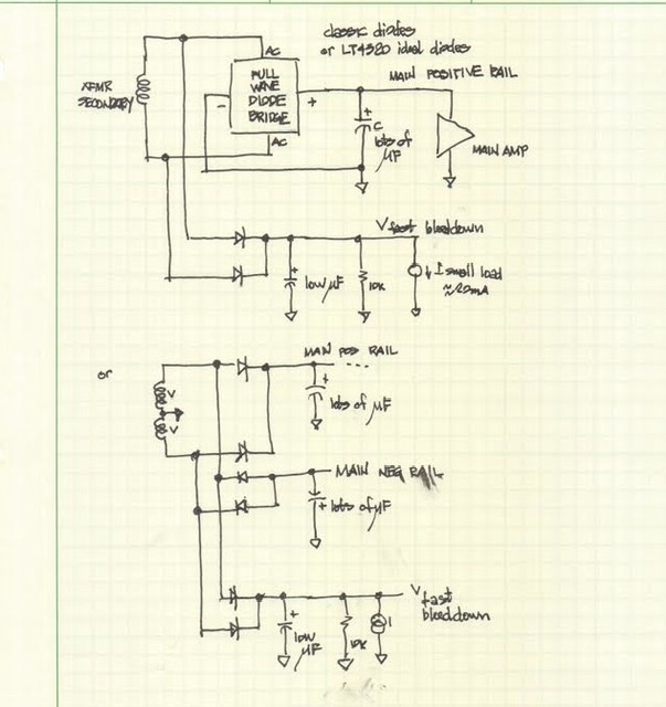
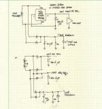
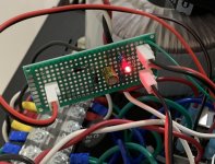
We have come up with a low cost and easy way to mod your RTR SSR to enable instant shutoff of the speaker connection to prevent turn off thump (or even could be used as a mute switch). The idea is simple - use a very low capacitance power supply so that when the main power switch is cut off, the power supply to the SSR is removed within a few cycles of mains 50/60Hz. We are using a half wave rectifier with a few 1N400x diodes connected to the amp power trafo secondaries. This feeds a circa 47uF capacitor with a 10k bleed resistor (I added a series LED to know when it is powered up). This supply has enough juice to power the SSRs which draw 20mA each. Here is a sketch of how to connect the low capacitance SSR PSU up (diagram courtesy jhofland). Make sure you connect the ground and AC input from the same trafo if using a dual monoblock setup.
So I tested it out and it works amazingly well. Literally, instant off on the sound when power switch is cut. Before it would take 10 seconds for the bulk rail caps to wind down and music would keep playing or in some amps, a turn off thump.
Diagram of how to connect the low capacitance PSU for the SSR:
Not much to this mod, maybe $1 worth of parts:
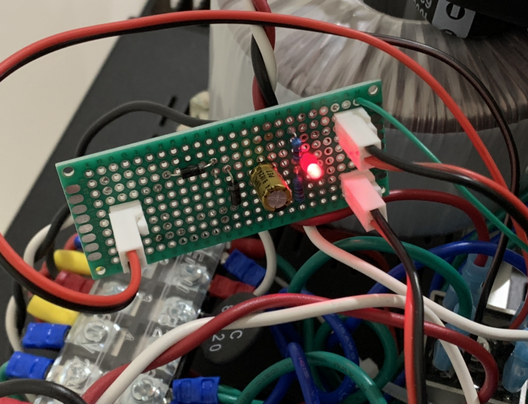
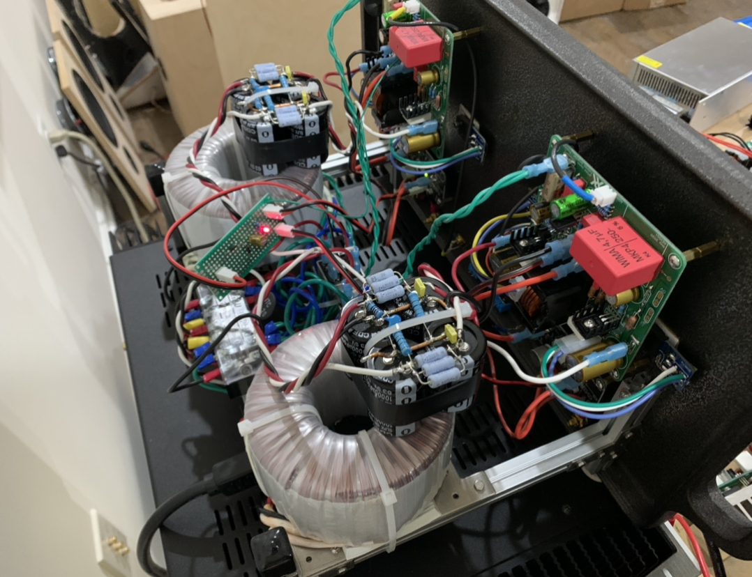
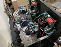
Installed on my FH9HVX:
Hi Folks,
We have come up with a low cost and easy way to mod your RTR SSR to enable instant shutoff of the speaker connection to prevent turn off thump (or even could be used as a mute switch). The idea is simple - use a very low capacitance power supply so that when the main power switch is cut off, the power supply to the SSR is removed within a few cycles of mains 50/60Hz. We are using a half wave rectifier with a few 1N400x diodes connected to the amp power trafo secondaries. This feeds a circa 47uF capacitor with a 10k bleed resistor (I added a series LED to know when it is powered up). This supply has enough juice to power the SSRs which draw 20mA each. Here is a sketch of how to connect the low capacitance SSR PSU up (diagram courtesy jhofland). Make sure you connect the ground and AC input from the same trafo if using a dual monoblock setup.
So I tested it out and it works amazingly well. Literally, instant off on the sound when power switch is cut. Before it would take 10 seconds for the bulk rail caps to wind down and music would keep playing or in some amps, a turn off thump.
Diagram of how to connect the low capacitance PSU for the SSR:
Not much to this mod, maybe $1 worth of parts:
Installed on my FH9HVX:
Attachments
I should mention that if you are running dual mono with two separate power transformers, make a separate low capacitance PSU board for each amp. That will avoid ground loops. I did as a quick test both SSRs powered from one side and luckily it works without hum. But I can’t guarantee that. It’s so cheap and easy to make there is no reason why not to make two separate ones.
Nice! Any chance this add-on will be integrated into the RTR protection board the next time you get a new batch made?
Just an AC sense circuit would be better for the next version, no? As soon as AC is off the circuit would cut the speaker? Don't know if it's ideal on the main speaker protection but on an off board like the softstart, it would be ideal.
Do
Do
In thinking about it more, I don’t think putting a low capacitance supply on board is such a great idea as it requires certain wiring and grounding considerations that the user needs to be very familiar with to work correctly. Not plug and play.
But anyone can build a half wave rectifier with a 22uF cap on a small vero board and try this out.
In effect, the low cap power supply with 2 diodes and a 22uF cap is an AC sense circuit as it is designed to cut off quickly - just the opposite of a real power supply meant to be stable and have reserves.
But an AC sense that trips the digital logic could be made as we have a digital enable already on the gen 2.
Wouldn't an AC sense circuit cut off the speakers between tracks, and when switching source, album, or at any time when there's no sound playing? If so, it seems like that would be too much switching on and off? Or maybe I'm confused about what is meant by an AC sense circuit.
Hmm that may all be true, but my thought is that if you're building a fully-loaded dual-mono amp, with 2 toroids, an SFP or other soft start board, 2 SLB (or 4! if you use the DIY Audio store PS boards) or other PS boards, 2 amp boards, and 2 speaker protection boards, it would be cool not to have to add 2 more boards into the mix, however small they are.
But then again, if putting this tiny PS on the speaker protection board is going to risk introducing buzz, hum, or other grounding problems, then yeah it's probably worth just building it on a separate board.
Why is that? Not questioning your judgement, just curious and trying to learn.In thinking about it more, I don’t think putting a low capacitance supply on board is such a great idea as it requires certain wiring and grounding considerations that the user needs to be very familiar with to work correctly. Not plug and play.
But anyone can build a half wave rectifier with a 22uF cap on a small vero board and try this out.
In effect, the low cap power supply with 2 diodes and a 22uF cap is an AC sense circuit as it is designed to cut off quickly - just the opposite of a real power supply meant to be stable and have reserves.
Hmm that may all be true, but my thought is that if you're building a fully-loaded dual-mono amp, with 2 toroids, an SFP or other soft start board, 2 SLB (or 4! if you use the DIY Audio store PS boards) or other PS boards, 2 amp boards, and 2 speaker protection boards, it would be cool not to have to add 2 more boards into the mix, however small they are.
But then again, if putting this tiny PS on the speaker protection board is going to risk introducing buzz, hum, or other grounding problems, then yeah it's probably worth just building it on a separate board.
AC sense on the transformer secondary that powers the SSR. Basically, the SSR is powered the usual way - from a clean high capacitance rail (typical output of a CRC for the main amp). There is another connection to the trafo secondary that is rectified and has a tiny cap and bleed resistor. When AC mains is on, this AC sense has a DC voltage which feeds an LED of an optoisolator. The optoisolator signal is fed to a comparator. When the AC mains is cut, the AC sense instantly drops on DC voltage since the capacitor is small and the bleed takes it down. The comparator the tells main SSR optoisolator to switch off. This is process is safer because the mains AC detection is optically isolated from the main circuit and you won’t have any potential ground loops or improper grounding issues as with simply putting a low capacitance PSU on board.
If I have this wrong, maybe Jhofland can chime in and explain it correctly. That’s how I understand the AC sense would be implemented to keep things “idiot proof”.
The reason I fear it is not easy is that it took me several tries to connect the compact PSU to the right ground location.
If I have this wrong, maybe Jhofland can chime in and explain it correctly. That’s how I understand the AC sense would be implemented to keep things “idiot proof”.
The reason I fear it is not easy is that it took me several tries to connect the compact PSU to the right ground location.
Last edited:
Ahh I see. The AC sense method you described was the first thing that came to mind, but then when I remembered the SSR is powered from a DC V+ rail, I thought that must incorrect. But I guess you'd just have to change some of the circuit and add AC sensing input and output connectors onto the board.
So why is the low cap PS a potential problem when it's integrated onto the SSR main board, but not when it's on its own little piece of perfboard?
So why is the low cap PS a potential problem when it's integrated onto the SSR main board, but not when it's on its own little piece of perfboard?
Last edited:
There have been quite a few people who have recently ordered the RTR SSR's from my shop. Some of you feeling a little frustrated at how long the shipments are taking. With COVID-19 delays, packages are taking 2-3 weeks for international orders, and sometimes up to 4 weeks in rare cases. Please note that since Etsy has switched to a policy of using a "Global Shipping" consolidator, the shipping seems to be taking about an extra week as the packages sit at a consolidation warehouse (typically in Philidelphia, PA or in New Jamaica, NY) in the US before departing overseas. The packages are relabeled with a new tracking number and can only be tracked by Etsy's website. The USPS tracking number that I placed on the packages only shows "Delivered" to the consolidating warehouse. There are a few benefits with this approach - the cost of shipping remains the same as if it were shipped via USPS First Class package with these important benefits: (1) it is tracked; (2) it is insured; (3) it is 99.7% reliable (those are my statistics based on 600+ shipments, I have lost 2). If you would like to utilize something faster for shipment - please contact me directly about your order before you place the order and I can offer you options such as Priority Mail Express or UPS Global Express. Be warned that they are very expensive.
I appreciate your patience.
Thanks,
X
I appreciate your patience.
Thanks,
X
Last edited:
I can confirm what xrk971 has said. I ordered something from America and it was stuck in New Jamaica for what seemed like for ever. It took nearly 2 months to arrive to me here in the Czech Republic. Ordering from China is much quicker.
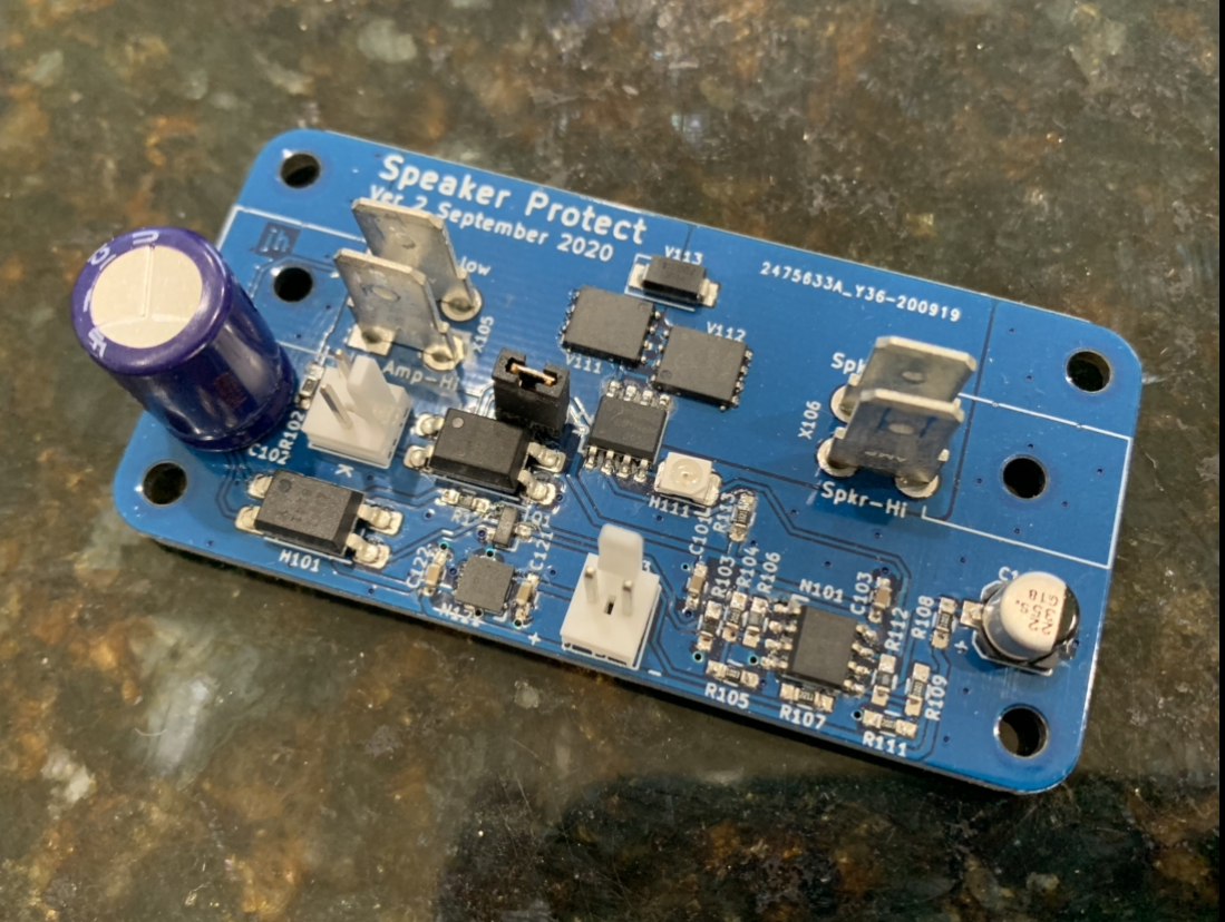
Prototype of Gen 2 RTR SSR
I just received a set of prototypes from Jhofland for the Gen 2. Features:
-150v MOSFETs so capable of handling almost any DIY amplifier power within reason (350w into 8ohms max)
-DC offset sense circuit isolated from speaker negative so bridged amps can be used
-remote enable via optically isolated open collector logic (bypass with jumper)
-remote enable can switch off instantly to prevent turn off thump using included (DIY) daughter board to generate quick shutoff signal from power transformer secondary
-same footprint as gen 1 board to allow upgrading.
Attachments

I just received a set of prototypes from Jhofland for the Gen 2.
I hope you still have Gen 1 boards available, X. 🙂
(I may have to order another replacement, as I may have blown up the one you sent me a few weeks ago. Unfortunately, I can't definitely say whether that SSR is - or is not - OK, as I am having problems with the SLB/AN 4R combo it's paired with. R18 on the SLB keeps smoking - after I connect up the AN 4R pcb to it. Hugh has already suggested a couple of component changes on the SLB - but it continues to happen. 🙁
He suspects this may be caused by an oscillation problem with the 4R circuit - I am now waiting for a Variac to arrive, so I can see whether the SLB oscillation still happens when the +/- DC rails are reduced to 15v.)
Andy
- Home
- Group Buys
- Ready-to-Run (RTR) SSR DC Speaker Protection and Delay GB