Not exactly. There will be an additional circuit to allow remote turn off. The rest will pretty much be the same. The current MOSFETs are good to 100v. I don’t think anyone here is playing with amps rails above 100v. It’s just that to get a new board made for a run of 100 units takes 3mo’s or more. But a PCB for DIY is maybe 3 weeks.
The negative passes through (same as GND) and can be done external to the board.
I am working with Jhofland on a new design and we have identified a new MOSFET, same footprint that can do 150v for higher power amps. The design will have galvanically isolated speaker -ve and amp GND (0v) so that this can be used for BTL amps as well and have remote shutoff/enable, and quick shutoff to prevent speaker thump upon power-down.
DIY project is even better. A PCB like SLB is perfect.
So the components could be customized to suit the individual requirements such like maxi amp power, rail voltage etc.
Looking forward to seeing it.
I am working with Jhofland on a new design and we have identified a new MOSFET, same footprint that can do 150v for higher power amps. The design will have galvanically isolated speaker -ve and amp GND (0v) so that this can be used for BTL amps as well and have remote shutoff/enable, and quick shutoff to prevent speaker thump upon power-down.
A prototype of the gen 2 has been built and is undergoing testing by jhofland. So far so good.
How do people feel about assembling their own SMT boards of the gen2?
Same footprint - upgraded features include SSR MOSFET that can handle 150v, remote enable, and instant off prevent turn off thump.
How do people feel about assembling their own SMT boards of the gen2?
Same footprint - upgraded features include SSR MOSFET that can handle 150v, remote enable, and instant off prevent turn off thump.
I should clarify that the instant off feature is only possible if you have something to control the enable logic input. Something like a very low energy storage PSU such as a small SMPS that shuts down quickly could be used to tell the enable to shut off or an MCU controlled PSU with soft start.
A prototype of the gen 2 has been built and is undergoing testing by jhofland. So far so good.
How do people feel about assembling their own SMT boards of the gen2?
Same footprint - upgraded features include SSR MOSFET that can handle 150v, remote enable, and instant off prevent turn off thump.
I'm okay with SMD. I'm getting 'better' with every new project that use SMDs.
A toaster oven uses IR elements and that takes a lot of time and can overheat your parts. Better off with a dorm style hot plate and small skillet. I use a $40 hot air pencil designed for SMT rework. A heat gun for shop use can work but air flow may be too great and it will blow your parts around.
I use something similar to this:
Hot Air Rework Station Kit with Digital Display SMD Desoldering Rework Station for BGA IC 700W 500°C Hot Air Rework Station Kit with Digital Display SMD Desoldering Rework Station for BGA IC 700W 500degC - - Amazon.com
Solder paste like this works. It’s relatively low temp of 138C will prevent parts from getting too hot. Use an IR thermometer for the hot plate.
Solder Paste Sn42/Bi57.6/Ag0.4 No-Clean Lead-Free Low Temperature Melts 138C 281F Solder Paste Sn42/Bi57.6/Ag0.4 No-Clean Lead-Free Low Temperature Melts 138C 281F - - Amazon.com
I have an SMT howto posted somewhere...?
Soldering SMD components
Making balanced output from single end
Last edited:
We would need to have interest and commitment of at least 50 fully assembled and tested units to make this a feasible group buy. The gen 2 will go for $55 ea (more complex and more expensive parts). Should I start a new GB interest list?
It might be possible to sell a very (no more than 12) hand-assembled boards at a higher price (TBD) if that was something people would be interested in.
It might be possible to sell a very (no more than 12) hand-assembled boards at a higher price (TBD) if that was something people would be interested in.
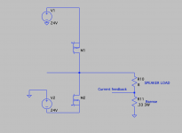
I am wondering if version 1 of the SSR circuit will work with my "imitation" F7 (First Watt) amp. As you may know, this amp does not ground the speaker directly, but rather has a current sense resistor in series with the speaker and ground. The current sense resistor supplies a positive feedback voltage to the input stage to increase the apparent damping factor of the output stage, which can theoretically approach infinity.
There is normally no DC offset at the speaker or across the sense resistor, so I am thinking the SSR would be OK in series with the high side of the speaker, but would like your opinion on this. The only thing different from a conventional amp is the presence of the sense resistor.
Attached is a simplified schematic of the output stage for reference.
Attachments
- Home
- Group Buys
- Ready-to-Run (RTR) SSR DC Speaker Protection and Delay GB