Looking real nice there
I wanted to ask you if you got a good deal on bulk amounts of the SB65, and from where in that case? I'm planning a smaller 2-way line-source and want to use the correct drivers already in the prototypes to get real world measurements before committing to making the cabs....
I didn't try to negotiate a specific bulk price, I just ordered them from SoundImports: DIY audio components and accessories - SoundImports march last year and i paid € 1.105,61 for 44 of them (I had 4 from small scale testing already). Seems to be the same price today.
YOu can also ask Fabrice at Compagnie Acoustique de Belgique, Compacbel for a quotation. He is in Belgium, but the drivers are shipped straigth from Denmark, where SB has them stored. Free shipping over 99 euros. I am not affiliated to him, just a happy customer.
I don't have a cat no =)
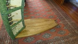
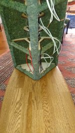
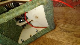
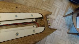
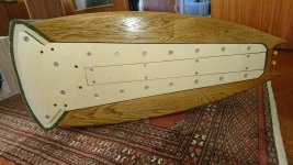
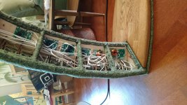
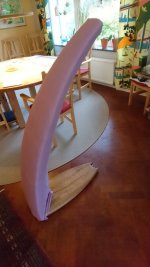
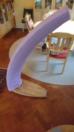
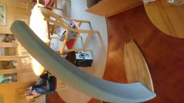
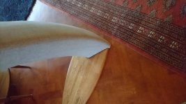
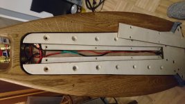
Now the bases are pretty much done and I like how they turned out. The speaker parts will be covered in 2 layers of fabric which will be mounted with velcro on the bottom. The velcro will be mounted on the ~ 1.5 cm deep platform seen in the third image.
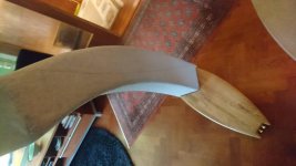
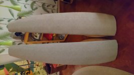
I think in hindsight it was unnneccesarily complicated to have the extra cable window on the bottom. I could have had the bottom in one piece and then just unscrewed the oak if I wanted to access the cables.
Now the bases are pretty much done and I like how they turned out. The speaker parts will be covered in 2 layers of fabric which will be mounted with velcro on the bottom. The velcro will be mounted on the ~ 1.5 cm deep platform seen in the third image.
I think in hindsight it was unnneccesarily complicated to have the extra cable window on the bottom. I could have had the bottom in one piece and then just unscrewed the oak if I wanted to access the cables.
Attachments
Last edited:
Some more progress:
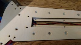
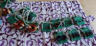
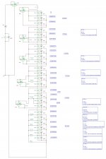
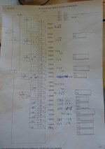
In theory, I have a network ready to mount in the speaker. Next step is to mount it and then test and see if it performs as I expect from the simulation.
I decided to make the network a bit more complicated by instead of using only resistors to use a series resistor + an inductor in parallel with a resistor. Reason being to take into account that the speakers have a rising impedance response.
Attachments
Last edited:
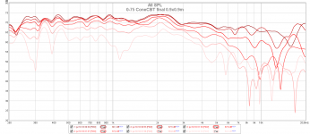
Shading network for the first speaker is done. Measures close enough to the target ratios that I'm satisfied with the result. It measures great too, so the next step is to fix the network for the other channel and then start sewing the fabric cover. 0-75 measurement is done indoors and while I tested the polar at this distance and height it measures pretty much the same everywhere which I really like.
Lessions learned though:
Lessions learned though:
- I should have used Molex Micro-fit Jr connectors instead of screw terminals. The screw terminals were cheaper but the testing of the network and connecting everything would have been more simple.
- I should have added probe points to the boards so I can easily measure the voltage.
- I should have included the PCBs in the cad drawing, they could have had them sized better and placed better on the spine.
- I should have used different colored sleeved cables for the positive and negative. Right now there is a small black line on the negative but with so many cables an all around color would have made everything easier.
- The network is probably unneccesarily complicated. I have individual shading for the top 8 drivers, shading them in sets of 2 would have been good enough.
Attachments
Last edited:
What a fantastic build and results!
I am so impressed with this.
I have had similar thoughts over the last few years - I even started a thread a few years back about a dipole line array using small full range drivers - but this is well beyond my initial thoughts!!
I clearly don't come often enough to the full range forums (spend most of my time in the multiway).
Can't wait to see how this turns out! So impressed.
A little progress:
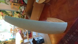
Not the final cover but a test to see if the pattern needs adjustment. The bottom will be nicer on the finished cover. While I like the pink color I'm leaning on a light grey cover to make it more compatible with other furniture.
One idea I've been toying with in my head though is to make the two rear fabric pieces a single color light grey but use a lighter or darker grey fabric for the front, or a patterned grey fabric. But since the final cover will most likely be two layers I'll wait until I make a finished light grey cover in the light grey color to see if I want to spice it up a bit.
Attachments
More progress:
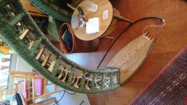
One channel is finished now. I like the result, I think it looks great =)
The fabric is mounted on the underside with velcro.
There is 1 layer grey stretchy acoustic fabric and then 1 layer of the grey outer fabric. I looked at linen as outer fabric but didn't find any thin enough with the right color so the final fabric is grey IKEA Lenda curtains .
.
One channel is finished now. I like the result, I think it looks great =)
The fabric is mounted on the underside with velcro.
There is 1 layer grey stretchy acoustic fabric and then 1 layer of the grey outer fabric. I looked at linen as outer fabric but didn't find any thin enough with the right color so the final fabric is grey IKEA Lenda curtains
.Attachments
- Home
- Loudspeakers
- Full Range
- CBT Dipole with SB65WBAC25-4