Much simplified but it will get you started.
The lower right hand resistor and the upper right one (the two 1k's) determine the gain of the circuit.
....
Try it. If you make the lower right resistor a 500 ohm then you will get twice as much signal at the output.
I did that. The output exhibits a larger swing but clips at the bottom. More current allowed through the circuit means the maximum current through the circuit is higher. This makes sense.
The two left hand resistors are there to pre-bias the transistor and set the 'operating point' such that the collector voltage sits at about 7 volts.
We can calculate those values once we decide (its our call) what collector voltage we want.
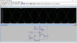
I will play around with the circuit a little and try to get answers to my questions. To start with, I changed the supply voltage to 9V. Since this will reduce the bias current into the base of the transistor, I decreased both bias resistors and got a decent output waveform with a bit of clipping at the bottom. On the test circuit I can adjust these to get low distortion.
Practically, if I build the circuit, do I need a high power ceramic resistor (maybe 10W) as the upper right resistor? Any other components needed so I do not burn anything up?
Attachments
Last edited:
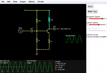
Let me duplicate your circuit in LTspice.
Wattage of resistors... here is a tip for you. Look at the supply voltage of a circuit as that tells you the highest voltage any part can see across it.
So you have 9 volts.
Now pick a wattage rating for any resistors such as 0.5 watt. From those two numbers we can calculate what the lowest resistance value is that you could use with 9 volts across it and still be within 0.5 watt.
Look at that chart I posted earlier.
R= Voltage squared divided by power and so we get (9*9)/0.5 which is 162 ohms.
So any 0.5 watt resistor higher than 162 ohms can not have its rating exceeded when used on 9 volts even if placed right across the supply.
The base bias resistors need to be low enough to be able to deliver enough base bias current to the transistor but not to low that they cause excess current consumption.
Also the lower they are and the more they load the signal source at the input.
If we make them to high (say 250k and 100k or even 2.5 meg and 1 meg then the base current for the transistor would be to small to bias it. You are getting into transistor theory and practice with that and 'current gain' of transistors.
Here is your circuit in Spice with voltages and waveforms. Notice the phase inversion. As the input goes up, the output goes down. It is 180 degrees out of phase.
Attachments
This is a redundance and adds nothing new.I did that. The output exhibits a larger swing but clips at the bottom. More current allowed through the circuit means the maximum current through the circuit is higher.
Throwing values at random into a simulator, with no clue why, teaches you NOTHING.I will play around with the circuit a little
Just by sheer chance.Since this will reduce the bias current into the base of the transistor, I decreased both bias resistors and got a decent output waveform with a bit of clipping at the bottom.
Circuits are not designed that way.
Simply calculate dissipated power.Practically, if I build the circuit, do I need a high power ceramic resistor (maybe 10W) as the upper right resistor? Any other components needed so I do not burn anything up?
Oh, I forgot, you can´t.
You stubbornly refuse to learn.
Unless, of course, this is just a trick to have everybody flying around you.
OK so I calculate dissipated power....
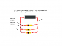
I should have done the calculation earlier, yes. W=I^2 * R . So one side is 35K Ohms and the other side is 2K Ohms. Assume current does not flow into the base, and assume the transistor is full open, zero resistance. For a potential difference of 9V, V=IR so as an upper bound we have I = 9/2000 = 0.0045 A. Is this correct? 0.0405 W
I should have done the calculation earlier, yes. W=I^2 * R . So one side is 35K Ohms and the other side is 2K Ohms. Assume current does not flow into the base, and assume the transistor is full open, zero resistance. For a potential difference of 9V, V=IR so as an upper bound we have I = 9/2000 = 0.0045 A. Is this correct? 0.0405 W
Assuming the transistor is not in circuit we have the 35k on one side.
Current is 9/35000 which is 0.257 milliamps.
Voltage across each resistor V=I*R so we get 25k*0.257e-3 which is 6.425 volts and 10k*0.257e-3 which is 2.57 volts. Remember the current is the same in each for a series circuit.
Add them together and we get the 9 volt total.
Power dissipation in each resistor is either the voltage squared divided by resistance or current multiplied by voltage. Both will give the same answer.
So the 25k dissipates 1.65 milliwatt. The 10k is 0.66 milliwatt. Pretty low")
If the transistor was removed (or the base open) then no current could flow in the 1k's. If the transistor was shorted collector to emitter then each resistor would see 4.5 volts across it. The power in each would 20.25 milliwatt
Your calculation of 9/2000 is correct at 0.0045A or 4.5 milliamp (can be written 4.5e-3).
0.0405W (40.5 milliwatt) is the total of the 2k's across 9 volt which is 20.25 milliwatt each.
Current is 9/35000 which is 0.257 milliamps.
Voltage across each resistor V=I*R so we get 25k*0.257e-3 which is 6.425 volts and 10k*0.257e-3 which is 2.57 volts. Remember the current is the same in each for a series circuit.
Add them together and we get the 9 volt total.
Power dissipation in each resistor is either the voltage squared divided by resistance or current multiplied by voltage. Both will give the same answer.
So the 25k dissipates 1.65 milliwatt. The 10k is 0.66 milliwatt. Pretty low
If the transistor was removed (or the base open) then no current could flow in the 1k's. If the transistor was shorted collector to emitter then each resistor would see 4.5 volts across it. The power in each would 20.25 milliwatt
Your calculation of 9/2000 is correct at 0.0045A or 4.5 milliamp (can be written 4.5e-3).
0.0405W (40.5 milliwatt) is the total of the 2k's across 9 volt which is 20.25 milliwatt each.
Thanks for explaining it so clearly. So Voltage can be seen as the capacity to provide a current?
Top rail as it were, is always at 9V and does not change, that is charge reservoir that will provide a current to any circuit connected to the positive +9V and the negative terminal of a the current source. Imagine a 9V battery with maybe 15 different high resistance wires running from the positive to negative terminal. Each positive end of the wire has access to the same charge store, but the amount of charge that runs through each wire each second (Amperes) will depend on the resistance of each wire in.
So much for Voltage.
There is not much current running across the circuit. I thought that the power dissipated would depend on the voltage across the resistor only, as it resists the large electric charge in the battery or power source. For power to be dissipated, current must run through the circuit: the more current runs through the resistor, the more power dissipated.
Sometimes these things are not explained clearly enough I think.
Most resistors are of the 0.5W category and should do the job. In the circuit I mentioned, the author is using 24V I think.
This design uses 15 Ohms and 24 V
DIY Class-A 2SK1058 MOSFET Amplifier Project
So in this case it is = (24 x 24 ) / 15 = 38 Watts! I see the need for a heat sink!
Top rail as it were, is always at 9V and does not change, that is charge reservoir that will provide a current to any circuit connected to the positive +9V and the negative terminal of a the current source. Imagine a 9V battery with maybe 15 different high resistance wires running from the positive to negative terminal. Each positive end of the wire has access to the same charge store, but the amount of charge that runs through each wire each second (Amperes) will depend on the resistance of each wire in.
So much for Voltage.
There is not much current running across the circuit. I thought that the power dissipated would depend on the voltage across the resistor only, as it resists the large electric charge in the battery or power source. For power to be dissipated, current must run through the circuit: the more current runs through the resistor, the more power dissipated.
Sometimes these things are not explained clearly enough I think.
Most resistors are of the 0.5W category and should do the job. In the circuit I mentioned, the author is using 24V I think.
This design uses 15 Ohms and 24 V
DIY Class-A 2SK1058 MOSFET Amplifier Project
Power dissipation in each resistor is either the voltage squared divided by resistance or current multiplied by voltage. Both will give the same answer.
So in this case it is = (24 x 24 ) / 15 = 38 Watts! I see the need for a heat sink!
NoSo Voltage can be seen as the capacity to provide a current?
NoTop rail as it were, is always at 9V and does not change, that is charge reservoir
Clumsy at best.that will provide a current to any circuit connected to the positive +9V and the negative terminal of a the current source. Imagine a 9V battery with maybe 15 different high resistance wires running from the positive to negative terminal.
Nocharge store,
Clumsy at best.but the amount of charge that runs through each wire each second (Amperes) will depend on the resistance of each wire in.
In fact it does.I thought that the power dissipated would depend on the voltage across the resistor only
Charge is irrelevant, what matters is voltage.as it resists the large electric charge in the battery or power source.
You still confuse charge, current and voltage.
You got *one* right.For power to be dissipated, current must run through the circuit: the more current runs through the resistor, the more power dissipated.
There is a method to learning, step by step.Sometimes these things are not explained clearly enough I think.
If you wildly jump from step to step at random, it will have no logic, it will not "stick".
You will ask 10000 times the same questions,over and over.
Most resistors are of the 0.5W category
IF you knew how to calculate it, even better, why and how, you could solve this yourself.In the circuit I mentioned, the author is using 24V I think.
As it stands, you have to ask about using 24V supply.
Now you change that to 23V or 25V,you have to ask again, because you can´t do it yourself.
And so on and on and on.
Suppose you switch supply to any value, volt by volt, from 9V to 24V, then you have to ask 15 times.
You repeat what you read verbatim but do not connect the dots for the big picture.Quote:
Power dissipation in each resistor is either the voltage squared divided by resistance or current multiplied by voltage.
You happy having the Forum flying around you, like moths around a candle, don´t you?
Last edited:
Thanks for explaining it so clearly. So Voltage can be seen as the capacity to provide a current?
Top rail as it were, is always at 9V and does not change, that is charge reservoir that will provide a current to any circuit connected to the positive +9V and the negative terminal of a the current source. Imagine a 9V battery with maybe 15 different high resistance wires running from the positive to negative terminal. Each positive end of the wire has access to the same charge store, but the amount of charge that runs through each wire each second (Amperes) will depend on the resistance of each wire in.
So much for Voltage.
There is not much current running across the circuit. I thought that the power dissipated would depend on the voltage across the resistor only, as it resists the large electric charge in the battery or power source. For power to be dissipated, current must run through the circuit: the more current runs through the resistor, the more power dissipated.
Sometimes these things are not explained clearly enough I think.
Most resistors are of the 0.5W category and should do the job. In the circuit I mentioned, the author is using 24V I think.
This design uses 15 Ohms and 24 V
DIY Class-A 2SK1058 MOSFET Amplifier Project
So in this case it is = (24 x 24 ) / 15 = 38 Watts! I see the need for a heat sink!
The voltage you have available and the resistance you place across that voltage determine how much current can flow. Voltage is the driving force. Whether you draw current from it depends on the load you place across it.
So in theory if you had a voltage source that could provide only 1 microvolt and if you could come up with a resistor of 1 micro ohm then 1 amp would flow. The power dissipation in the resistor would be 0.00000000000001 watts.
Your 9 volt battery with many different resistance wires would as you say see a current in each wire that depended only on the resistance of that wire. You might have 0.5A in one, 3A in another and another with 15A. The total sum of all the currents in all the wires (18.5A) would equal the current flowing in from the battery.
That Class A amplifier will run very hot. If you set the preset to give 12 volts at the output as shown then you have 12 volts across the 15 ohm, not 24 volts. So the power dissipated in the 15 ohm is (12*12)/15 which is 9.6 watts. The FET also sees the same power dissipation because the resistor and FET are in series and the same current flows through both.
Setting the preset to give 12 volts allows the amp to clip symmetrically. If you alter the bias point to say 8 volts then the power dissipation in each part changes. You now have 16 volts across 15 ohms which is 17 watts. The current is 1.06 amp. The FET has 8 volts across it and dissipates 1.06*8 which is 8.48 watt.
The balance of power has changed
by shifting the bias point.The total power dissipation of the amp is increased. We have 19.2 watts total biased to 12 volts and over 25 watts biased at 8 volts.
I think we can all agree that Class A amplifier will run very hot. Apparently MOSFETs have different characteristics than BJT transistors, I somehow missed that.
I am varying the values of the resistors in the circuit while keeping the total resistance in each branch the same: the lower resistor does make a difference to the circuit, I need to find out why.
Removing the lower resistor, that is, setting resistance to infinity does have an effect on the circuit that cannot be restored by changing any other set of resistors.
Class A power amplifiers run hot because of the high currents needed to drive a speaker but remember all small signal stuff like preamps are Class A but they run cool/cold because the currents can be low.
The big difference between the FET and the ordinary transistors are that FET's are 'voltage driven' and transistors are 'current driven'. That simply means that to turn a normal transistor on you need to to have current flowing in the base/emitter junction.
Super simplified... if you feed a current of 1 milliamp into the base emitter junction of a transistor and that transistor has a current gain of 100 then you would see 100 milliamps flowing in the collector/emitter path if it was connected across a suitable power supply.
The FET gate (a bit like the base) draws essentially no current but instead responds to voltage. If you have enough voltage between gate and source then the FET conducts between Drain and Source. Increase the gate voltage and it conducts more but the gate is not taking current from what is biasing it (that is super simplified in case anyone disagrees)
The transistor B-E junction will always limit out at about 0.7 volts across the junction. In other words words you can not force that voltage higher. All that happens is more current flows and the transistor conducts more.
The FET G-S voltage can be varied up to the limits of the FET specification, typically up to 15 volts or so for the FET in your amp. No DC current flows in G-S path. At high frequency AC things change a bit and the whatever is driving the FET gate has to be able to charge and discharge the gate capacitance (which isn't much).
The FET in that Class A amp is a 'Lateral FET' which are great for audio and they are different to the more common power MOSFET's.
If you like simulating circuits (and its a great way to learn) then why not try LTspice... click my signature line to get started
The big difference between the FET and the ordinary transistors are that FET's are 'voltage driven' and transistors are 'current driven'. That simply means that to turn a normal transistor on you need to to have current flowing in the base/emitter junction.
Super simplified... if you feed a current of 1 milliamp into the base emitter junction of a transistor and that transistor has a current gain of 100 then you would see 100 milliamps flowing in the collector/emitter path if it was connected across a suitable power supply.
The FET gate (a bit like the base) draws essentially no current but instead responds to voltage. If you have enough voltage between gate and source then the FET conducts between Drain and Source. Increase the gate voltage and it conducts more but the gate is not taking current from what is biasing it (that is super simplified in case anyone disagrees
)The transistor B-E junction will always limit out at about 0.7 volts across the junction. In other words words you can not force that voltage higher. All that happens is more current flows and the transistor conducts more.
The FET G-S voltage can be varied up to the limits of the FET specification, typically up to 15 volts or so for the FET in your amp. No DC current flows in G-S path. At high frequency AC things change a bit and the whatever is driving the FET gate has to be able to charge and discharge the gate capacitance (which isn't much).
The FET in that Class A amp is a 'Lateral FET' which are great for audio and they are different to the more common power MOSFET's.
If you like simulating circuits (and its a great way to learn) then why not try LTspice... click my signature line to get started
- Home
- General Interest
- Everything Else
- Questions about electric current and audio circuits.