I think we experience the same. When one sees consumer electronics almost daily then SMPS is a curse word. Since I worked in power electronics I noticed SMPS there and thought the known issues would occur but no these were of required quality and rarely failed. Still many colleagues favored transformers ")
When I got a few NOS Mascot SMPS for free I also saw European quality and these were also built to function for a long time. It can be done, unfortunately it does not count for the majority we see in audio devices. Even Lynn devices fail and it is very often the so favored SMPS they implemented that fails. Yes the SMPS Lynn also states to be a choice for quality
When I got a few NOS Mascot SMPS for free I also saw European quality and these were also built to function for a long time. It can be done, unfortunately it does not count for the majority we see in audio devices. Even Lynn devices fail and it is very often the so favored SMPS they implemented that fails. Yes the SMPS Lynn also states to be a choice for quality
Last edited:
The fake SMPS had all of the European, US, Aus and NZ EMI/RFI approvals stamped on it (U/L, PCT GS, SA, CE, C-tick, etc, etc) but obviously because industry is self-regulating these days
Yeah, it's down to "do you trust the brand"...
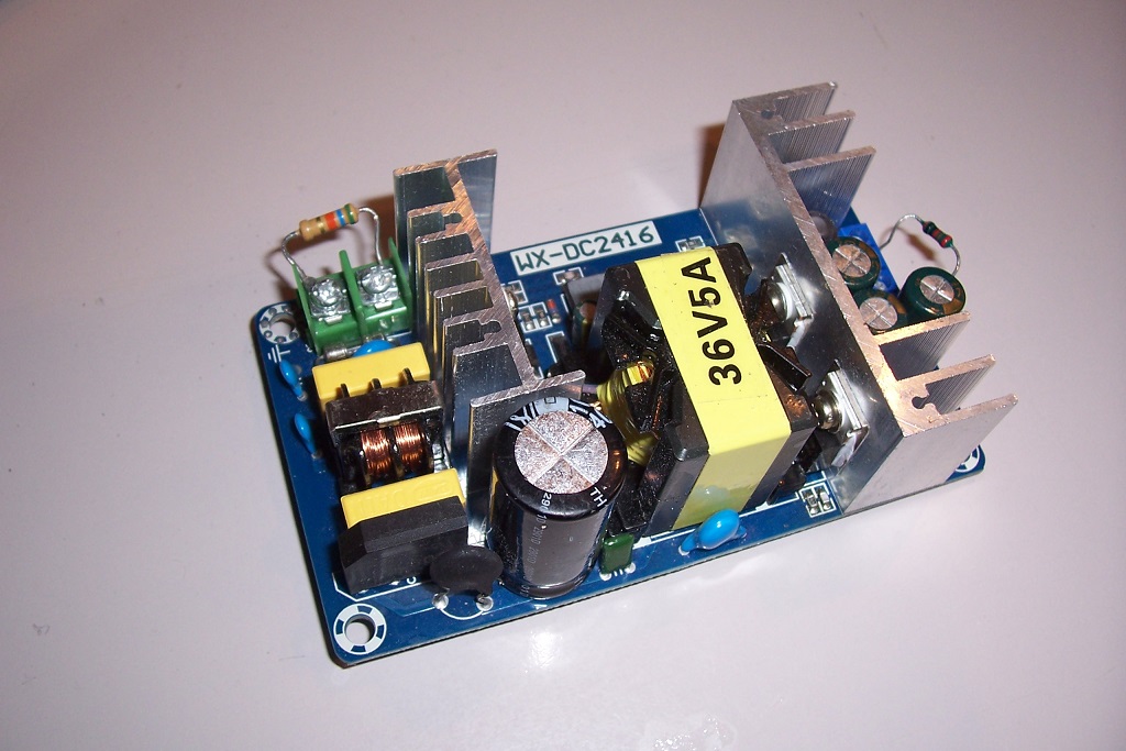
I have had a look at my supply:
I tested it, and it did indeed put out some crap: the FM tuner of my lab was unaffected, but it stands on the upper shelf of my instrument wall, about 2 meter away from my bench top.
Exploring the E-vicinity (without contact) with an oscilloscope probe showed several volts of switching hash 20cm away.
A small portable FM radio was seriously disturbed tens of cm away, and a spectrum analyser centered on the FM band confirmed that the noise level was significantly raised.
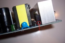
Upon examination, I noticed that both heatsinks were isolated but floating. Since the MOS sink is capacitively coupled to its drain, it spat out a huge switching E-field.
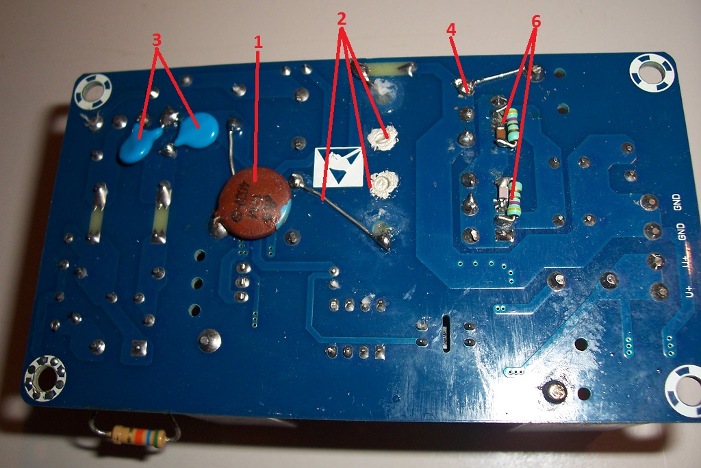
This was the most obvious, low-hanging fruit, and I fixed its AC potential, using a Y cap to the - supply input. A direct connection would be possible but the cap has the same result, but is safer in case of accidental contact.
#1 in this pic:
As a result, the LF/MF/HF E-hash was reduced, but some substantial residues were still present. The cause was the transformer. Its ferrite core is floating, and is also coupling switching hash.
As I didn't want to unsolder it, I grounded its core by milling the insulation underneath, and fixed the potential by attaching drain-wires connected with two drops of conductive ink #2.
Now, the E-hash was very substantially reduced. For a good measure, I also bypassed the AC side of the rectifier bridge to the -, with Y caps, to avoid AM modulation of the hash by the mains #3, and I connected the secondary diodes heatsink to the output GND #4.
Results? The E-environment was very clean... but the VHF perturbations and the FM reception were completely unchanged.
Looking more closely, I determined that VHF disturbances came almost exclusively from the secondary side, in particular the rectifying diodes.
They are schottky types, and have individual RC snubbers, but they nevertheless generated significant amounts of VHF noise.
The problem is that the snubbers address the ringing issues, but probably aggravate the VHF emissions: they are loaded with a resistive 47R, which do not mitigate the singular discontinuity caused by the rectification.
The diodes are quasi-perfect, do not "stick" due to the Trr, but even ideal diodes working on an ideal sinewave act as frequency multipliers because of the waveform discontinuity.
The leakage inductance of the transformer could have mitigated the issue by softening the transition, but the resistive load presented by the snubbers prevented it. The 47R is high enough to allow VHF to escape.
The first thing I did was to reintroduce some inductance, in the form of ferrite beads (~0.25µH) threaded on the center leg of each diode: #5 in this Pic:
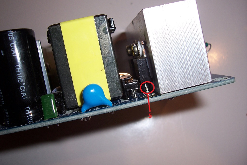
The result was spectacular: a ~80% reduction of the problems
The next step was to shunt the diodes, to confine the emission to a very small loop.
I added much more aggressive snubbers (4.7R/4.7nF): #6
This appeared to practically solve the problem: noise was still visible on the SA, but the radio worked undisturbed with its antenna nearly touching the supply.
The solution is not perfect (a redesign of the supply would be necessary), but it works, with some caveats: the snubber should be optimized to disipate less (the resistors become seriously hot) and probably ring less: with these values, a severe but relatively low frequency ringing is present.
It is probably possible to adopt less extreme values, and to add another RC to damp the secondary, but the effect is going to be mostly cosmetic, like the original: what is really important is in fact not visible
I tested it, and it did indeed put out some crap: the FM tuner of my lab was unaffected, but it stands on the upper shelf of my instrument wall, about 2 meter away from my bench top.
Exploring the E-vicinity (without contact) with an oscilloscope probe showed several volts of switching hash 20cm away.
A small portable FM radio was seriously disturbed tens of cm away, and a spectrum analyser centered on the FM band confirmed that the noise level was significantly raised.
Upon examination, I noticed that both heatsinks were isolated but floating. Since the MOS sink is capacitively coupled to its drain, it spat out a huge switching E-field.
This was the most obvious, low-hanging fruit, and I fixed its AC potential, using a Y cap to the - supply input. A direct connection would be possible but the cap has the same result, but is safer in case of accidental contact.
#1 in this pic:
As a result, the LF/MF/HF E-hash was reduced, but some substantial residues were still present. The cause was the transformer. Its ferrite core is floating, and is also coupling switching hash.
As I didn't want to unsolder it, I grounded its core by milling the insulation underneath, and fixed the potential by attaching drain-wires connected with two drops of conductive ink #2.
Now, the E-hash was very substantially reduced. For a good measure, I also bypassed the AC side of the rectifier bridge to the -, with Y caps, to avoid AM modulation of the hash by the mains #3, and I connected the secondary diodes heatsink to the output GND #4.
Results? The E-environment was very clean... but the VHF perturbations and the FM reception were completely unchanged.
Looking more closely, I determined that VHF disturbances came almost exclusively from the secondary side, in particular the rectifying diodes.
They are schottky types, and have individual RC snubbers, but they nevertheless generated significant amounts of VHF noise.
The problem is that the snubbers address the ringing issues, but probably aggravate the VHF emissions: they are loaded with a resistive 47R, which do not mitigate the singular discontinuity caused by the rectification.
The diodes are quasi-perfect, do not "stick" due to the Trr, but even ideal diodes working on an ideal sinewave act as frequency multipliers because of the waveform discontinuity.
The leakage inductance of the transformer could have mitigated the issue by softening the transition, but the resistive load presented by the snubbers prevented it. The 47R is high enough to allow VHF to escape.
The first thing I did was to reintroduce some inductance, in the form of ferrite beads (~0.25µH) threaded on the center leg of each diode: #5 in this Pic:
The result was spectacular: a ~80% reduction of the problems
The next step was to shunt the diodes, to confine the emission to a very small loop.
I added much more aggressive snubbers (4.7R/4.7nF): #6
This appeared to practically solve the problem: noise was still visible on the SA, but the radio worked undisturbed with its antenna nearly touching the supply.
The solution is not perfect (a redesign of the supply would be necessary), but it works, with some caveats: the snubber should be optimized to disipate less (the resistors become seriously hot) and probably ring less: with these values, a severe but relatively low frequency ringing is present.
It is probably possible to adopt less extreme values, and to add another RC to damp the secondary, but the effect is going to be mostly cosmetic, like the original: what is really important is in fact not visible
Attachments

It is clearly under-dimensioned. I tested it at 5A, but I don't think it would last for very long under such conditions: most of the parts became uncomfortably hot.
It would be suitable for a class AB amplifier drawing 5A for a full power sinewave output, but not for a class A amplifier (unless some derating is applied)
It would be suitable for a class AB amplifier drawing 5A for a full power sinewave output, but not for a class A amplifier (unless some derating is applied)
I assume this is a flyback converter. 180W with a flyback of that size? Never! Flybacks are the simplest and cheapest suitable for small power applications. Increasing power shows their limitations: Very high ripple current in secondary rectifiers and caps, poor utilisation of ferrite core, high component stress, mediocre efficiency and lots of noise and spikes.
For power above 100W there are much better choices like LLC, for instance.
For power above 100W there are much better choices like LLC, for instance.
Thanks Elvee. I have the same SMPS and made the modifications that you suggested. I didn't change the snubbers for the diodes, they seem to have lower values in my variant (5.6 Ω, maybe an improved version?).
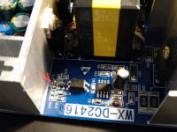
The transformer ferrite core I scratched lightly, glued a wire to it and applied conductive paint to the bare wire.
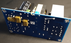
To change the output voltage, resistor R18 (1500 ohm) can be changed (shown with red arrow in second picture). I used a 1580 ohm resistor and now the output voltage is around 33.8 V (I wanted it to be below 35V). To get a lower output voltage, use higher value resistor. You can also calculate the desired output voltage from the resistor divider R18 and R20 (20 kΩ) and the reference voltage, which seems to be 2.7 V. So e.g. for 24 V output, R18 should be 2.32 kΩ.
The transformer ferrite core I scratched lightly, glued a wire to it and applied conductive paint to the bare wire.
To change the output voltage, resistor R18 (1500 ohm) can be changed (shown with red arrow in second picture). I used a 1580 ohm resistor and now the output voltage is around 33.8 V (I wanted it to be below 35V). To get a lower output voltage, use higher value resistor. You can also calculate the desired output voltage from the resistor divider R18 and R20 (20 kΩ) and the reference voltage, which seems to be 2.7 V. So e.g. for 24 V output, R18 should be 2.32 kΩ.
Attachments
LED bulbs are regulated under FCC Part 18, (not Part 15) and the limits set are not sufficiently stringent to prevent RFI: http://www.arrl.org/files/file/RFI/Light_Bulbs.pdfAnd the RFI problem isn't just on the FM band. If your a ham radio operator today, in many neighborhoods you are lucky to have ANY "clear" reception in the LF/MF/HF bands. The SMPS in many(most) LED bulbs also help ruin that.
Get an SMPS from an established manufacturer like Meanwell - they may be more expensive, but are also more likely to apply due diligence for EMI and safety regulations. BTW, it takes a LOT of EMI to hash up an FM broadcast. AM is more sensitive in that regard, but there's not much going on with AM these days.
There are a fair number of companies manufacturing SMPS that don't know what they're doing, and may not care, with blatant mistakes re EMI and safety - their only concern is making it cheap... Many also don't know how to properly lay out the PCB for an SMPS. This can directly impact safety, efficiency and other operating characteristics of the supply.
On the average day in the US, almost half the US population turns to an AM radio for news, weather or talk. NPR's "All Things Considered" has almost 15 million daytime listeners!but there's not much going on with AM these days.
Regrettably, BMW, MB, Volvo are not equipping their new cars with AM radio, you have to stream via iHeart.
I listen to AM Talk Radio every day.On the average day in the US, almost half the US population turns to an AM radio for news, weather or talk. NPR's "All Things Considered" has almost 15 million daytime listeners!
Regrettably, BMW, MB, Volvo are not equipping their new cars with AM radio, you have to stream via iHeart.
WPHT 1210 AM and WNPT 990 AM.
The shows I tune into provide me with real news, logic-based commentary, and less bias.
Point being that you find those signals (if they’re strong) in almost every other device, it is not only tuners that suffer from it. With tuners it just becomes more clear quite fast as it has a showstopping effect.
Please pay attention to cheap LED lighting as well. Some are true garbage transmitters.
Long ago HiFi sounded better in the evening as mains voltage was cleaner. Today a set can sound different at times because of stray in.
Please pay attention to cheap LED lighting as well. Some are true garbage transmitters.
Long ago HiFi sounded better in the evening as mains voltage was cleaner. Today a set can sound different at times because of stray in.
Last edited:
Also, JP, I've seen a turntable, a Dual DD, go crazy when a nearby cellphone rings.Point being that you find those signals (if they’re strong) in almost every other device, it is not only tuners that suffer from it.
Please pay attention to cheap LED lighting as well. Some are true garbage transmitters.
The tonearm would lift off the record, speed would change - all due to RF triggering the Dual's internal IC chips.
- Home
- General Interest
- Everything Else
- SMPS killed my radio reception