The problem is that current flows via the load resistor and through the B-E junction of the PNP device straight into the NPN B-E junction.
In other words you have effectively connected the two loads of the PNP devices to ground via two series diodes.
The NPN device in this condition will just turn hard on.
In other words you have effectively connected the two loads of the PNP devices to ground via two series diodes.
The NPN device in this condition will just turn hard on.
We need a bit more detail...
At a basic level and as your circuit is drawn you could achieve what you want by replacing the PNP's with NPN's and deriving their base drive from the collector of the original NPN.
But we need more detail, voltages, what the loads are and so on.
At a basic level and as your circuit is drawn you could achieve what you want by replacing the PNP's with NPN's and deriving their base drive from the collector of the original NPN.
But we need more detail, voltages, what the loads are and so on.
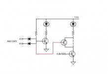
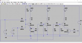
I attached a more detailed schematic. It is diode transistor logic (DTL). A simple AND gate that needs to see both "A" and "B" high to lit the led. But "A" -and "B"- are also used to control their independent drivers. The problem is that I want to keep the independent commands off when "A+B" is on. So my novice thinking was to insert these PNP. As said the load will be around 150mA fed from 5V or so.
Attachments
OK, so your first transistor could really do with a diode in the emitter lead. This is to raise the threshold the transistor turns on at.
Without it and you rely on the diodes pulling the base voltage below that needed by the transistors own B-E forward voltage. Which could be a bit indeterminate... the circuit is on the edge of working/not working under all conditions.
So that gives us a reliable working AND gate with the LED on when A and B are high (or floating).
When do you want the second LED to be on?
Is that LED to light when A is high no matter what B is doing?
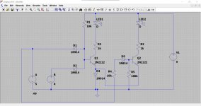
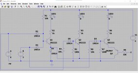
This shows the LED1 operating under control of A and B and LED2 lights only when A is high.
Without it and you rely on the diodes pulling the base voltage below that needed by the transistors own B-E forward voltage. Which could be a bit indeterminate... the circuit is on the edge of working/not working under all conditions.
So that gives us a reliable working AND gate with the LED on when A and B are high (or floating).
When do you want the second LED to be on?
Is that LED to light when A is high no matter what B is doing?
This shows the LED1 operating under control of A and B and LED2 lights only when A is high.
Attachments
"This shows the LED1 operating under control of A and B and LED2 lights only when A is high." Yes, and another driver to light LED3 only when B is high. So far so good but I need to ask two things:
1. Does LED2 (and LED3) stay off when LED1 is on?
2. Is the emitter diode necessary when psu is 5V and logic level is ~3V?
1. Does LED2 (and LED3) stay off when LED1 is on?
2. Is the emitter diode necessary when psu is 5V and logic level is ~3V?
LED2 and LED3 work independently. If A is high then LED2 is on. If B is high then LED3 is on. If both are high then both are on (together with LED1).
A 3 volt logic level isn't the problem, it is the logic 0 that could cause a problem because the input diodes can not be guaranteed to pull the base down enough to turn the transistor off. The diode doesn't pull the base to zero, it can only pull it to around 0.6 volts which might leave the transistor still on a little bit.
If the inputs are left floating then the defaults are LED1 on, LED's 2 and 3 are off.
It all works OK on 3 volt logic levels but I would recommend high gain small signal transistors. The 10k base resistors can be reduced if needed.
Attachments
Great! Hoping I'm not wasting your time, I have a couple more questions:
1.Can I place pull down resistors at D1,D2 to keep LED1 off when A and B are floating?
2. Can I substitute 2N2222 for BD135 (hfe 250). It's an overkill but cheaper and fits better on my PCB.
3. Just to clarify. A PNP in series with Q2 (Q3) to cut off LED2 (LED3) is not possible?
1.Can I place pull down resistors at D1,D2 to keep LED1 off when A and B are floating?
2. Can I substitute 2N2222 for BD135 (hfe 250). It's an overkill but cheaper and fits better on my PCB.
3. Just to clarify. A PNP in series with Q2 (Q3) to cut off LED2 (LED3) is not possible?
You can use pull down resistors but they will need to be around 1k5 (or lower) in value.
High gain transistors are best if the load is only an LED. BC546, that kind of thing. You would have to try the BD135 and see how it worked.
An important question is what the load current. Is it just an LED as you show or is it something else?
Adding more control to LED2 or 3 can be done but it all depends on what the control signals to do that are.
For example if A and B are high and all LED's are on do you then want further individual control of (say) LED2 with a High or Low signal for on?
I'll look in later")
High gain transistors are best if the load is only an LED. BC546, that kind of thing. You would have to try the BD135 and see how it worked.
An important question is what the load current. Is it just an LED as you show or is it something else?
Adding more control to LED2 or 3 can be done but it all depends on what the control signals to do that are.
For example if A and B are high and all LED's are on do you then want further individual control of (say) LED2 with a High or Low signal for on?
I'll look in later
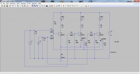
This adds an NPN transistor to give separate control. When point C is high (along with point B) then LED3 will light.
If you use a PNP then point C needs to go Low to light the LED.
If you use a PNP then point C needs to go Low to light the LED.
Attachments
I spent the whole evening to get into LTspice but I see you were also working. I appreciate you help very much! So, based on your schematic this seems to do what I want: only A=1>only LED2=on, only B=1>only LED3=on and A+B=1>only LED1=on. Could you kindly check it when time allows?
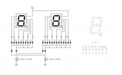
The circuit I'm trying to design is a seven segment digital display so the load is several relatively high current LED in parallel
The circuit I'm trying to design is a seven segment digital display so the load is several relatively high current LED in parallel
Attachments
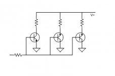
NO answer possible unless you state voltges involved.The schematic shows one NPN and two PNP with independent loads but common base resistor. All I can find is about transistors in parallel so I thought to ask here if there is anything wrong with this arrangement.
Any answer without that is just a wild guess or flipping a coin.
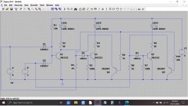
Quick cobble together...
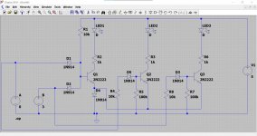
1/ LED's are now high current types.
2/ Load resistors much lower value.
3/ Shottky diodes for the input as these have a lower forward voltage.
4/ Base drive resistors reduced to allow more base current. You need to experiment here.
5/ PNP transistors remove the base drive voltage to give the logic sequence you want.
Last post for tonight
I've attached the .asc file that will run directly.
Attachments
I couldn't ask for more! Thanks a lot Mooly!
Complete schematic for this is a pain to draw. See attachment for a simplified version. Logic level ~3V. Vcc is not written in stone. Can be anything convenient.
NO answer possible unless you state voltges involved.
Any answer without that is just a wild guess or flipping a coin.
Complete schematic for this is a pain to draw. See attachment for a simplified version. Logic level ~3V. Vcc is not written in stone. Can be anything convenient.
Attachments
- Home
- General Interest
- Everything Else
- Basics on transistor drivers