This thread has not gone to Mars; if anything, it has begun to straighten out some misconceptions about how transformers should be wired. It might confuse some people, but IMO this thread is necessary. We're talking about basic safety and code requirements.
I assume the original thread starter has gotten the answer to his original question, so hopefully there is no threadjacking going on.
Attached is typical transformer wiring. It is also possible to have corner grounded and center tap grounded delta windings, which produce what is called a "wild leg", but this is waaaay beyond the scope of this thread, and they are certainly not typical.
Three phase transformers are permitted to be wired as floating secondaries, as you stated, given that certain requirements are met. As well, single phase transformers are permitted to be wired as floating secondaries, given that certain requirements are met. In the residential application given above, these requirements are not met. So can it be? Yes. Is it legal? No.
This is why the isolating transformer may ship without any bond. It is application dependent as to whether or not the secondary should be bonded.
Not sure what you mean by the safety relay. Perhaps you are referring to a ground fault interrupter ?
Attachments
Originally posted by cbcassell
I would answer your question as follows: An AC current would flow through his (her) body.
You would ask: How much current?
I would answer: Worst case, the current that is flowing through the wire that connects the secondary with the EGC in your diagram.
Would you agree?
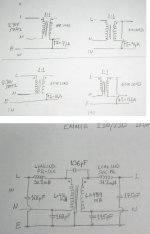
This afternoon I tried to measure this current (see attached photo, upper part) on an isolation transformer with floating secondary.
Upon connecting the jumper to the working secondary, the current jumps to around 250 microAmperes and then levels off to a steady state current of 12 microAmperes *.
I did the measurement 10 times. The 250uA is the mean. Spread is from 125uA to 400uA. Save for the integration time, make it 1000uA=1mA.
I also measured the electrical characteristics of this transformer (attached photo, lower part).
When floating, both ends of secondary measure 175pF toward the earth (shield).
The energy stored in a 200pF cap charged to 322V (322Vpeak=230Vrms) is 1micro Joule. This is really unimportant for discharging.
This value will increase though with the length of the attached cable.
I still think that a floating secondary is the way to go when dealing with repairs on hot chassis.
Please have a look at my post#18.
I performed some more measurements, which confirm the opinion of zigzagflux (excellent link to the TRUTHpdf, thank you) that noise isolation is better on grounded secondaries than on floating, but on this, I will report some days later.
* Polarity matters marginally . It is better to check the polarity of the coils and ground the secondary to the “Neutral” side.
Regards
George
Dear CrisWhat happens if someone touches a device with no safety ground connected to your floating power supply and simultaneously touches a device that is properly grounded to the building power system?
I would answer your question as follows: An AC current would flow through his (her) body.
You would ask: How much current?
I would answer: Worst case, the current that is flowing through the wire that connects the secondary with the EGC in your diagram.
Would you agree?
This afternoon I tried to measure this current (see attached photo, upper part) on an isolation transformer with floating secondary.
Upon connecting the jumper to the working secondary, the current jumps to around 250 microAmperes and then levels off to a steady state current of 12 microAmperes *.
I did the measurement 10 times. The 250uA is the mean. Spread is from 125uA to 400uA. Save for the integration time, make it 1000uA=1mA.
I also measured the electrical characteristics of this transformer (attached photo, lower part).
When floating, both ends of secondary measure 175pF toward the earth (shield).
The energy stored in a 200pF cap charged to 322V (322Vpeak=230Vrms) is 1micro Joule. This is really unimportant for discharging.
This value will increase though with the length of the attached cable.
I still think that a floating secondary is the way to go when dealing with repairs on hot chassis.
Please have a look at my post#18.
I performed some more measurements, which confirm the opinion of zigzagflux (excellent link to the TRUTHpdf, thank you) that noise isolation is better on grounded secondaries than on floating, but on this, I will report some days later.
* Polarity matters marginally . It is better to check the polarity of the coils and ground the secondary to the “Neutral” side.
Regards
George
Attachments
sorry
in our schools this does not apply ...
and also the word supervised also does not apply anywhere ....
i am sor this no longer a question of opinion its simply a diference of how mains installations are worked out ....
in europe most of houses had single phase power supply .... since this is coming from some central three phase power supply keeping a tie between earth and neutral exactly where th income of the mains comes inside the house ( location of the main earth probe also ) is done for 2 reasons
1- to preserve balance between phases at all times
2- then to provide aditional potection since any leak to earth can blow the fuse
now days newest houses have 3phase power supply and inside towns ground is diferential then on the other hand 30mikro amper leakage relay is a must and not optional
still in country side and mostly where cables from midle voltage 4.5kv to low voltage trafos are quiet long the electric company still uses a tie between N and earth ....
so all this you say is probably for some other standard ....
all electrical products in europe come with a CE marking and have no "options" only yes or no things ....
we dont have people for supervision as you describe it ...... we stoped doing that years ago since some of them fell asleep on duty .....
after that standards are changed ....
since also terms like "under supervision" dont really apply in our schools and univercities ....
happy european regards sakis .....
PS
george ....we hope that your theory has gone to mars now after all you have heard here but please be kind enough to answer my question and let us now why you originally wanted to have this type of transformer for your audio system ....
thank you .....
Sakis
In post#4 You can read that during a monitoring of main's electrical noise that I was performing, I thought that it might be good to monitor the noise of the output from this isolation transformer that I had in my lab.
Well, it was then that I noticed these strange voltages which stoped me and the rest is the story of this thread, which I find of great value.
Regards
George
Nice measurements, George. Thanks for the info.
One question: the 136pF capacitance from primary to secondary has me a little suspicious. With the E-shield grounded, it should reduce this value to nearly immeasurable values. We test transformers from 1 to 10,000 kVA on a daily basis, and capacitance is one of those measurements. For large transformers, the interwinding capacitance is obviously quite large. Put in the E-shield in, and this capacitance is reduced to absolutely nil.
Maybe the shield wasn't grounded for the measurements, or it wasn't guarded out?
Attachments

ok .....
thanks george ....with all that theory i missed that
i will excuse my shelf from your thread now but before id like to thank all the people involved since various approach and information provide us with a lot of extra knowhow ....
i will close my argument by saying that i find the voltage in post no4 absolutelly normal since the output of the trafo is floating
thank you all for your input
Thanks to every body for comments, information. diagrams, and actual measurements.
Could somebody please provide connection diagrams for Ultra isolation transformers / noise canceling transformers which have multiple shields in them? something like a diagram posted by member "cbcassell"
My second question is can we safely connect a home desktop PC to a balanced power output isolation transformer?
regards
acid:
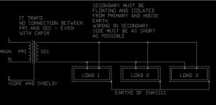
What standard (number) is this from? It looks like a specialized application. Also, it's curious they have not shown where the chassis bonds are supposed to go. I would expect they go right back to 'E'; you would think they would show that on the drawing.
That almost looks like something closer to shore power or medical grade equipment.
zigzagflux
The chassis bond go nowhere. The "isolated" earth bond is mandatory for more than one device/chassis connected. If you have a single chassis, no earth is connected. Remember: from the secondary of trasformer, we are working on a totally ISOLATED (trasformer) and totally FLOATING system. No hot points. No reference to main. No well-defined live. No well-defined neutral. No earth. Only 2 wires carring 240V voltage. System isolated from the world (like a car electical system).
You have current trough human body only in one situation: you touch the 240v wires in the same moment.
yes, medical grade equipment. it is isolated and floating.
for standard number, please wait... I'm searching.
EDIT: shot-circuit (or over-current) protection is mandatory on the secondary side of IT. It protect from double earth failure (with more than one device) also.
pooge
Yes, but this system can continue to work safetly with a earth fault.
zigzagflux
Italian standard CEI 64-8 doesn't limit this at medical use. It limit the lenght of wires (high capacitive reactance), and type of cable (double insulation).
Assuming that, I can use it at home.
Greece standard may be different.
acid_k2 said:pooge
Yes, but this system can continue to work safetly with a earth fault.
How is it safe if you are at earth potential and you touch the chassis that is contacted by a 240v line??
Are you talking double insulated here?
Double insulated is allowed in U.S., but with strict standands not likely attainable by a DIYer building his own equipment, and power amps are rarely, if ever, double insulated. My take is that if you provide a three-pronged outlet on the secondary, the ground prong better be connected to earth at the service panel.
acid:
If you would like to try it at home, go for it; you certainly don't need my approval, especially since I have little knowledge of standards outside of the U.S. I think I've made my point clear enough about what is allowed in the states---it's only an observation that there is a lot of consistency internationally. So you're prepared to purchase double-insulated cable and/or chassis? You're braver than I thought, Han Solo")
I will say this, though. IEEE standards are essentially international, and they have a lot to say about grounding power systems (Green Book 142) and sensitive electronic equipment (Emerald Book 1100). The subject matter covers surge protection, personnel safety, fault coordination, noise immunity, harmonics, shielding, the list goes on.
As a general rule (barring Medical, Shore, or Battery Equipment, which carries a different set of goals), IEEE is fairly consistent in their requirements, as well as their recommendations. Power systems are more robust and quiet when they are effectively grounded. I have do doubt we can all come up with esoteric exceptions to this idea, but they are few and far between (and should not be found in the residential environment).
An audio system that has excess noise and/or hum, which is subsequently 'fixed' by the installation of a floating secondary isolation transformer, is a compromised system that has had a band-aid put on it. The audio system needs to be modified or connected properly such that these problems are eliminated without the need for a floating power source.
For what it's worth, I will eventually install an iso-xfmr for my system. It will be solidly bonded to earth. Whether or not it's balanced, I won't say....
If you would like to try it at home, go for it; you certainly don't need my approval, especially since I have little knowledge of standards outside of the U.S. I think I've made my point clear enough about what is allowed in the states---it's only an observation that there is a lot of consistency internationally. So you're prepared to purchase double-insulated cable and/or chassis? You're braver than I thought, Han Solo
I will say this, though. IEEE standards are essentially international, and they have a lot to say about grounding power systems (Green Book 142) and sensitive electronic equipment (Emerald Book 1100). The subject matter covers surge protection, personnel safety, fault coordination, noise immunity, harmonics, shielding, the list goes on.
As a general rule (barring Medical, Shore, or Battery Equipment, which carries a different set of goals), IEEE is fairly consistent in their requirements, as well as their recommendations. Power systems are more robust and quiet when they are effectively grounded. I have do doubt we can all come up with esoteric exceptions to this idea, but they are few and far between (and should not be found in the residential environment).
An audio system that has excess noise and/or hum, which is subsequently 'fixed' by the installation of a floating secondary isolation transformer, is a compromised system that has had a band-aid put on it. The audio system needs to be modified or connected properly such that these problems are eliminated without the need for a floating power source.
For what it's worth, I will eventually install an iso-xfmr for my system. It will be solidly bonded to earth. Whether or not it's balanced, I won't say....
pooge said:
How is it safe if you are at earth potential and you touch the chassis that is contacted by a 240v line??
Are you talking double insulated here?
Double insulated is allowed in U.S., but with strict standands not likely attainable by a DIYer building his own equipment, and power amps are rarely, if ever, double insulated. My take is that if you provide a three-pronged outlet on the secondary, the ground prong better be connected to earth at the service panel.
240V line (in the secondary of trasformer) is NOT referred to anything. It's not referred to main (live and neutral), and it's not referred to earth. It's floating. If you touch the chassis that is contacted by a 240v wire, the wire goes at earth potential. No current (or better:very small current for capacitance between cables and earth) flows through your body.
Double insulated cables, assemblies and devices are common here (Italy).
For italian standard, double insulation is more secure than earth connection.
The ground prong better be connected to earth at the service panel?
If you need isolation, no. We are talking about an isolation trasformer. But you could connect it at a separate earth point. Earth at the service panel (or at grid high-tension transformer for italian grid) is connected to neutral wire of the grid.
acid_k2 said:
240V line (in the secondary of trasformer) is NOT referred to anything. It's not referred to main (live and neutral), and it's not referred to earth. It's floating. If you touch the chassis that is contacted by a 240v wire, the wire goes at earth potential. No current (or better:very small current for capacitance between cables and earth) flows through your body.
Then you better not touch something that is earthed at the same time!
acid_k2 said:
The ground prong better be connected to earth at the service panel?
If you need isolation, no. We are talking about an isolation trasformer. But you could connect it at a separate earth point. Earth at the service panel (or at grid high-tension transformer for italian grid) is connected to neutral wire of the grid.
The purpose of an isolation transformer is NOT for ground isolation, and grounding the secondary does not inhibite the common mode filtering of the transformer. And you CANNOT connect it at a separate earth point unless that separate earth point is bonded to the ground at the service panel in the US without violating safety codes. In the US, the neutral is connected to the earth wire at the service panel also.
- Status
- This old topic is closed. If you want to reopen this topic, contact a moderator using the "Report Post" button.
- Home
- General Interest
- Everything Else
- Question about how to wire an Isolation Transformer