I just checked one of mine for the same signals to get a baseline.
Conditions- loopback BNC to BNC, input and output floating, 1 KHz, level 14V 50 Ohms source (spl 75), TP 2 out output board clip lead to chassis. (do not connect before boot is complete).
Thanks so much Demian for all the effort and guidance. I'll try to replicate these baseline measurements and will report back.
A few new player's questions if you don't mind (you might be overestimating my skill level):
- You mean putting the 1121 in special function 75 when doing the measurements, correct?
- "TP5 ac coupled at high gain": do you mean setting the probe in 1:1 mode?
Special 75 sets the output impedance to 50 Ohms. That reduces its sensitivity to external noises. TP5- AC coupled with high gain to see the noise. I did use 1:1 on the probe for more sensitivity. And 20 MHz band limit to lower the noise of the scope re: input. There isn't anything that's liable to oscillate at 100 MHz in a stock unit. The 5534's won't get there. Is there a radio station near you?
Today I tried to reproduce the baseline measurements (loopback BNC to BNC, input and output floating, 1 KHz, level 14V 50 Ohms source (spl 75), TP 2 out output board clip lead to chassis). Distortion measured was around 0.0025%.
I didn't know how to get a scaled output of the input signal so measured TP1 on the source board instead.
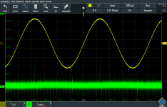
First picture: source TP1 (yellow) vs. TP5 on source board (green) (AC coupled, 20MHz bandwidth).
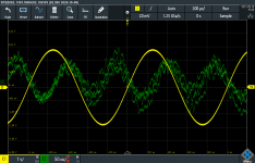
Second picture: source TP1 (yellow) vs. Monitor out (green).
I didn't know how to get a scaled output of the input signal so measured TP1 on the source board instead.
First picture: source TP1 (yellow) vs. TP5 on source board (green) (AC coupled, 20MHz bandwidth).
Second picture: source TP1 (yellow) vs. Monitor out (green).
Attachments
That all looks typical for a stock unit. The second harmonic is the dominant and can be addressed on both source and analyzer. I think its mostly from the analog multipliers.
You can see the sample pulse on TP5 but its mostly lost in all the RF noise you are getting.
I have noticed that there can be some noise across the grounds in these which is annoying. The balanced to balanced is an effort to reduce it. I get those random glitches as well. It may simply be random noise from something getting it.
I hope Tuesday I'll be able to post some simple upgrades as a first step. I'll be gone for a week after Tuesday so any more documentation will need to wait until I return.
Thanks Demian! Looking forward to any tips you could share on upgrades. No rush...
One additional note: besides the glitches on TP5, I noticed several glitches in the monitor out signal as well (see att.), not sure if that's expected for a stock unit.
One additional note: besides the glitches on TP5, I noticed several glitches in the monitor out signal as well (see att.), not sure if that's expected for a stock unit.
Attachments
the scope may need to float to ground, do not use chassis fro scope ground.
source and output using separate power supply, using board ground for troubleshooting
1121 has five bands for source output, try other frequency such as 20Khz, if 20khz signal is stable, it is band problem, there are 10 caps on the board for tuning each band, you may want to measure them, also you can remove u10 to disable feedback , the output will go up to 10 volt but stable.
you can find more information on the menu.
- Home
- Design & Build
- Equipment & Tools
- Boonton 1121 Audio Analyzer: some questions