Hi folks,
I've recently scored my first audio analyzer on Ebay, a Boonton 1121. The device was listed as untested but after starting up and performing a loopback test it seems to work reasonable well (still have to do performance tests though). A few quick questions:
1) When checking loopback distortion at 1KHz (3V) the result seems acceptable for an uncalibrated unit: 0.003%. However at this frequency the distortion number is not very stable, every few seconds it jumps to 0.006% and back again. This behavior is most noticeable at 1KHz, at other frequencies I haven't seen many glitches. Any tips on where to start troubleshooting, could this be a capacitor issue?
2) The device came without the adapter cable that is mentioned in the user manual. Am I right in assuming that when testing an audio amplifier speaker output, I should connect the speaker + to input high and speaker - to input low? So that means I would need to make a cable with 2 BNCs on one end (with only the core pin connected) and 2 speaker jacks at the other end?
Thanks!
Quick update:
Trying to eliminate potential causes for the glitches in the distortion reading, I connected the output of an external audio generator (1KHz, 3Vrms) to input high. This resulted in a very stable reading, albeit with higher distortion.
So I concluded that this eliminated the analyzer section as the potential cause and started focussing on the oscillator. I checked the electrolytic caps on the Source board (A6) and some appeared to have somewhat high ESR. So I replaced all 100uF caps but while this resulted in a lower distortion reading (around 0.0025%), the glitches are still present.
More troubleshooting to do... `
On the 1121 the source connections are completel floating when the float button is pressed. Same for the input. For a meaningful loopback connect the outputs to the inputs using 2 BNC cables, float the output and do not float the input. This should chase most extraneous noise from the measurement. The two sides have separate isolated power supplies. Engage the 30 KHz filter to get a better fix on the source distortion separate from wideband noise. The best measurement will be just below 3V. Once the range changes the internal noise floor will limit your measurement.
Carefully tweaked you can het .0006% at 3V. However most are closer to .009% or so.
You will need to make up some cables to get the best use from it. Let me know if you need details on the cabling etc.
Carefully tweaked you can het .0006% at 3V. However most are closer to .009% or so.
You will need to make up some cables to get the best use from it. Let me know if you need details on the cabling etc.
Thanks for the helpful tips, Demian! The loopback with 2 BNCs resulted in lower noise and the distortion reading (1KHz, 3V) dropped to 0.0023%. The quality of the BNC cables may not be optimal so I'm sure this can be lowered further.
However, the problem of distortion reading being unstable with peaks to 0.006% is still there. Here's a quick video: IMG_2219.mov - Google Drive
Note that this behaviour only occurs with source frequency set around 1KHz. When changing frequency to <800Hz or >1200Hz the glitches disappear.
PS. Yes, if you could share more info on cabling that would be much appreciated!
I think what you are seeing is the oscillator having tuning problems. Try this-
set it to 1 KHz. Select frequency- it should be 1.000.00000000? If it jumps it may be the oscillator tuning issue. The oscillator is disciplined by the internal micro. If a cap or resistor is at its tolerance limit or worse the system will have trouble keeping it on frequency.
Another diagnostic is to look at the monitor out with a scope and see what pops up.
There should be an extender board inside so working on these is pretty easy.
There are upgrades, many of which are simple parts swaps that help.
Moving the I/O to the front is not that difficult and may make sense depending. Mine is connected through a ST1200 test panel so the front connectors are not used for connections. Yours looks really clean. All of the units I have and have seen have been somewhat beat. Some ex military.
Looks like you were right!
I hooked up the source output to my frequency counter and indeed the frequency jumps a bit when set at 1 KHz (but not at other frequencies). I've checked resistors around the tuning circuit and some of the 0.1% resistors are close or over the tolerance limit (the electrolytic caps I already replaced). I'll order some replacement parts and see if that will solve the issue.
This would be a good opportunity to order some additional parts for the upgrades to the 1121. I've followed your work on these upgrades in other threads with great interest, for example the PDF with modifications to the input board. Are there other modifications that are relatively simple that you would recommend?
Thanks in advance.
Another two possibilities- the Jfets (buy a handful to have them around) and the caps. The caps are more likely to be out of spec. What you can do to see if its tuning anywhere near correct is to check pin 33- fine tune the trim voltage. Set the frequency step to 1 Hz and then step up and down with the buttons to see what its doing. You should get a sense for where the voltage should be.
The input board mods make the most immediate difference and can be done with no soldering. change the inpurt opamps and the diff summing opamp. The diff opamp seems to be optimally an AD797. I'm using some LME4910 for the inputs but those are discontinued. I got a few from China that were fakes. AD797 is not optimal there. The OPA1611 might work OK but you will need adapters.
You can ditch the TL072 and jumper into out. The new opamps have much better DC performance.
Let me think and look for other quick performance/usability mods.
Thanks! I'll order a few more spare parts and hopefully I'll be able to narrow down the cause for the tuning problem.
A few more quick questions:
1) Looks like the original Jfets (J-108) are obsolete in through-hole package. Is there a specific alternative I should look for?
2) Do you recommend the OPA1611 for the input board mods over the OPA134 (as mentioned in the 1121 mods thread)?
A few more quick questions:
1) Looks like the original Jfets (J-108) are obsolete in through-hole package. Is there a specific alternative I should look for?
2) Do you recommend the OPA1611 for the input board mods over the OPA134 (as mentioned in the 1121 mods thread)?
You can find the J108's on eBay. Mouser has J109's https://www.mouser.com/ProductDetai...fYs_9kbwWC44J0qvICHRyNAHQzbqqg9xoC1JcQAvD_BwE They are a perfectly fine alternative.
For a stock PCB the OPA134 should be fine. I have a mod that reduces the noise on the input board but I'm not sure the effort was worth it. Most locations would benefit from lower noise low distortion opamps. I have not tried the 1611 or 1612 yet. I'm not sure how they will work.
However I have a very early unit that only has some opamp upgrades but has really low (.0006%) residual distortion. The newer units do not seem to be quite as good even with upgrades and I'm not sure why.
Finally an update after a short break...
I tried replacing the out of spec 0.1% resistors but that did not fix the problem. I've checked capacitors C14-17 and C19-22 out of circuit and they seem within tolerance (except for C17 that has slightly high capacitance, just out of spec). The electrolytics have already been replaced.
The trim voltage behavior on pin 33 when stepping up/down 1 Hz seems consistent between 1000Hz and other source frequencies as far as I can tell.
Any tips on next steps? Should I check the J108's and if so, what should I look for specifically? Basic function and matching on resistance?
Thanks in advance!
Is the trim voltage constant? Noise or transient would explain the blips I think. I'm surprised a .1% resistor would have changed much. Finding a specific bad fet is not easy. You can check the RDS on but maybe by stepping through and watching the fets switch you can see which fet pairs may be bad. The trim voltage will jump with each fet switch and jump a lot when a bad fet doesn't switch. It could be a help. I have one 1120 here that someone did a lot of fet swapping on its oscillator. Its in poor shape after that abuse and despite a lot of efforts still seems to have a bad connection somewhere. Be careful reworking the board. They are somewhat fragile.
Thanks Demian! Here's a sample of tuning voltage measurements at pin 33 starting at 1000 Hz with 1Hz steps.
Screenshot
Screenshot
Last edited:
That's pretty slick. Did you write a little program for that?
You can see from the big steps where the fets switch. What is the tune voltage at 800Hz? Does the voltage fluctuate when the frequency is at 1 KHz? I think there is a limit on the correction range of the voltage and maybe its close to a limit at 1 KHz.
You can see from the big steps where the fets switch. What is the tune voltage at 800Hz? Does the voltage fluctuate when the frequency is at 1 KHz? I think there is a limit on the correction range of the voltage and maybe its close to a limit at 1 KHz.
No program, just manual measurements to discover any patterns (still trying to make sense of how the source board works).
The voltage fluctuates a little bit around 1 KHz (between 3.627-3.636V).
The tuning voltage range at 800 Hz is similar (2.7-4.3V) although the steps are a little bigger (-0.31V versus -0.25V) when increasing frequency with 1 Hz.
The voltage fluctuates a little bit around 1 KHz (between 3.627-3.636V).
The tuning voltage range at 800 Hz is similar (2.7-4.3V) although the steps are a little bigger (-0.31V versus -0.25V) when increasing frequency with 1 Hz.
Quick update: I started replacing the JFets with new J109s in batches but this did not fix the issue.
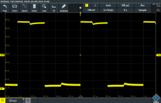
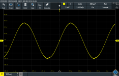
As I was running out if ideas, I decided to do a number or measurement at the various test points on the source board A6 using my oscilloscope (with TP3 a a ground reference). This gave some interesting results (see attachements):
- There is clear distortion in the waveform at TP1 and TP3.
- Notch in square wave at TP8.
- Very noisy signals at test points TP5, TP6 and TP7
Would I be right in concluding this points to a defective IC in the sample and hold circuit? Any tips for next troubleshooting steps? Thanks.
Attachments
I need to check some details on your unit. There are 3 major generations. The first gen has the source and output boards sharing ground with the rest of the unit. The second and later (like yours) have it isolated/floating and drive the output as bridge tied load. That can be really confusing to work with. You need to set the output to floating and then reference TP3 as ground for your measurements. Then both plus and minus will move. The scope photos suggest the unit ground tp3 is moving and the output may have one side grounded or the whole circuit is floating.
In light of that the waveforms are not to far off I think but worth looking again. The measured distortion is at least 80 dB below what the scope is showing.
Going back to the original issue- unstable distortion reading lets look at two things-
First the output waveform from the distortion- at the monitor jack. Look at it referenced to the source. Does it show something relating to the fluctuating distortion?
Second, look at the noise at the monitor out for internal noise sources-
start with the input shorted and grounded, then disconnect from ground and just short the inputs. These do have a log of noise across the chassis in come cases, and see what noise you get. Then connect to the output with the output at 0 volts/muted. This will show noise leaking from source supplies.
A third step that need a really good source (Victor?) to confirm the noise is in the source/output board.
Thanks Demian!
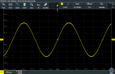
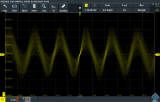
Yes, definitely a complex circuit to troubleshoot... I'll find some time later this week to do additional tests but here's another quick scope capture at test point TP5 with output float set to ON and with the probe ground lead attached to TP3. Just to avoid confusion: scope was incorrectly set to 1:1 instead of 1:10 so voltage levels are off.
Yes, definitely a complex circuit to troubleshoot... I'll find some time later this week to do additional tests but here's another quick scope capture at test point TP5 with output float set to ON and with the probe ground lead attached to TP3. Just to avoid confusion: scope was incorrectly set to 1:1 instead of 1:10 so voltage levels are off.
Attachments
I just checked one of mine for the same signals to get a baseline.
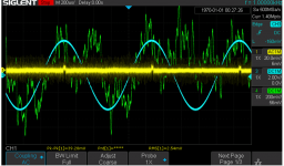
Conditions- loopback BNC to BNC, input and output floating, 1 KHz, level 14V 50 Ohms source (spl 75), TP 2 out output board clip lead to chassis. (do not connect before boot is complete).
Sine wave (blue) is the input monitor. I'll send a note later on how I detived it. Its a simple mod. Distortion (green) wave is the monitor out in distortion mode with the 30 KHz filter engaged. Yellow is TP5 ac coupled at high gain. You can see the feedthrough from the sample pulse (2 mV/div actually) on a 1.4V DC signal. This is the amplitude control to the analog multiplier. This unit gets .001% in this loopback mode but it has been tweaked a lot.
its important to make sure the signals and grounding are correct.
I get a clean square wave on TP8. Let us know what progress you make.
Attachments
Hi kris,
You're in good hands with Demian. 🙂
If I'm interpreting correctly, you have your scope probe set to 1:1 and your display suggests a noisey 100MHz sine wave.
I highly recommend using x10 scope probe setting, because the large capacitance of x1 can provoke opamp oscillation, what you might be seeing on the scope. If I'm compelled to use x1 because I'm desparate for added sensitivity, I'll often clip a 220 ohm resistor to the probe clip and probe the circuit through the resistor; the added resistance is usually sufficient to stop oscillation.
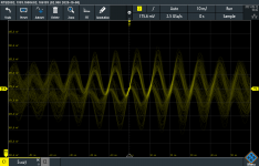
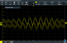
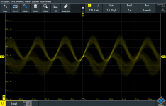
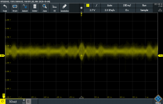
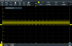
Thanks BSST, the probe was set to 10:1 but the scope itself to 1:1. Just tried with with correct setting but still seeing the noisy 100MHz sine wave at TP5 (also with output set to float). There is some amplitude modulation going on as well which I noticed when adjusting time base.
I'm not seeing the notches in the sine wave at TP1/TP2 anymore though and there's a clean square wave at TP8. 😕
Thanks for the tips btw, I was not aware of the risk of opamp oscillation.
I'm not seeing the notches in the sine wave at TP1/TP2 anymore though and there's a clean square wave at TP8. 😕
Thanks for the tips btw, I was not aware of the risk of opamp oscillation.
Attachments
- Home
- Design & Build
- Equipment & Tools
- Boonton 1121 Audio Analyzer: some questions