I plan to use a hot wire cutter to cut XPS foam to make speaker horn moulds.
Wire size about 0.5 mm, needs ~5 amps.
A 1 metre cutter in nichrome is ~5 to 6 ohms - so ~25 V and 125 watts.
That is easy and reasonably safe with a transformer.
In fact I even made a hot wire cutter similar to this as a one-off project for a friend's factory to cut broadloom plastic cloth.
It was decades back so I don't even remember the power requirements but commercial units are similar to what I calculate so I don't think I'm too far out.
The idea for the new project is an improved circuit that controls the power to reduce idle losses and allow closer tolerances.
It should be not too hard to monitor both the current and volts thru the wire and calculate the resistance, to use in a feedback loop to keep the temperature constant.
Anyone seen a circuit to do this?
The obvious way is a simple micro-controller but maybe a simple all analog circuit would work.
Or other ideas?
David
If you look online for Hot Wire PWM then you will find a lot of ideas.
PWM is Pulse Width Modulation. That is a method of basically reducing the effective voltage by turning the power on & off at a very high speed.
It is used because it is a very efficient method of control. When semiconductors are switched on & off then very little energy is wasted so there is very little heat produced in the semiconductor.
If you are trying to control voltage using a "linear" power supply then reducing the output voltage is done by dissipating the unwanted voltage as heat. This is wasteful of energy & requires big heatsinks to stop burning out the semiconductor.
PWM is described by duty cycle - the percentage that power is switched on in a given cycle period.
A duty cycle of 100% means that the voltage is on all the time & not turned off.
A duty cycle of 75% means that the voltage is on for 75% of the time & off for 25% of the time.
A duty cycle of 50% means that the voltage is on for 50% of the time (half the time) & off for 50% of the time (half the time).
A duty cycle of 25% means that the voltage is on for 25% of the time & off for 75% of the time.
A duty cycle of 0% means that the voltage is not on at all - off for all the time.
You can buy ready made PWM circuits on eBay at low cost.
Regards,
Brian.
Hi Brian
I try not to be too specific in the first post, just to be leave the discussion open to 'outside the box' ideas.
But I have some familiarity with PWM circuits and had expected that that was the way to do it.
However, I had not tried to search on exactly "Hot Wire PWM", thanks for the recommendation.
My idea is to hit the wire with ~40 V for 10 msec pulse and then measure the current at ~5 V.
The current increases as the wire cools so when the current exceeds some threshold then hit it with another power pulse.
I can do the measure with either a cheap micro-controller or a simple comparator and potentiometer.
I will have a closer look at some of the search hits and see what's easiest.
Best wishes
David
to get useful data you shouldn't use a NiCr wire, but pure metal like tungsten or eventually steel, their resistance is 2x at 300° and 3x at 600°. NiCr has only 1/20 of this temp coefficient.
Temperature Coefficient of Resistance | Physics Of Conductors And Insulators | Electronics Textbook
It will be better to use a regulated DC supply for continuous power and easier measurement.
The current is then proportional to 1/temp or 1/R. You do not need the 5V reference voltage.
.A simple comparator can control the duty cycle every 10ms.
You can dial in the temperature like on a soldering station.
On the contrary, he MUST use Nichrome so he can get predictable results and resistance does not vary all over the place while working.to get useful data you shouldn't use a NiCr wire, but pure metal like tungsten or eventually steel, their resistance is 2x at 300° and 3x at 600°. NiCr has only 1/20 of this temp coefficient.
FWIW I use Constantan which has an even LOWER temperature coefficient, go figure.
Those alloys were specially developed for that.
Besides, Tungsten is incredibly expensive (and hard to work with) and iron will rust, oxidize and eventually burn.
Resistor specific alloys get some surface oxide which is stable and protects the main bulk of wire.
Constantan can even be soldered with regular Electronic solder, go figure.
...NiCr has only 1/20 of this temp coefficient.
I was just about to check the Temp Coefficient of Resistance of Nichrome, thanks.
...DC supply for continuous power and easier measurement.
...A simple comparator can control the duty cycle every 10ms.
I don't understand your proposal, a DC supply doesn't usually have a duty cycle.
...Resistor specific alloys [are] stable
The stable oxides are why I planned to use Nichrome but I think "bansuri" has a point, since I plan a temperature feedback system an increased TCR would actually be helpful.
I checked and it is actually possible to buy Tungsten wire, it's 10x the price of Nichrome, expensive but less ridiculous than I expected.
Kanthal perhaps?
Best wishes
David
Last edited:
I use titanium wire for strength and use an old toroidal transformer from a dead power amplifier to heat it. I added a simple three turn secondary to the transformer to feed the hot wire. To adjust the heat at first I just adjusted the secondary turns. My first version was an E-I transformer of much larger size fed from a variac.
I use titanium wire...
What do you use your cutter for?
What thickness wire?
I just discovered there is a whole subculture of DIYvapers who basically need to heat up wire, who knew?
They have the same divide between open loop systems like yours and temperature controlled systems like I propose.
They confirm that Nichrome is difficult for closed loop because of the small TCR (Kanthal even more so, damn).
They recommend Stainless Steel, and Titanium should work too.
The vapers use low power so the inefficiency of a linear controller is no problem for them AFAIK.
Now to look at resistivity of SS versus Ti, and I have W as a last resort.
Best wishes
David
Last edited:
I was just about to check the Temp Coefficient of Resistance of Nichrome, thanks.
I don't understand your proposal, a DC supply doesn't usually have a duty cycle.
DC-supply / MOSFETswitch / heaterwire / shunt to measure current / gnd.
comparator controls the Fet switch off when current is below preset and temperature reached.
That is your own PWM.
Best wishes
Bansuri
Last edited:
....That is your own PWM.
OK, now I see what you mean.
The rationale of my scheme was that I only need to regulate a low power circuit, just the low volt test current rather than the more powerful heat phase.
So losses should theoretically be lower than your scheme but either should work.
(Your scheme is simpler if you have a spare power supply to use up.
") )
)The implementation I had in mind was to make the heat phase as simple as possible, not even filtered just direct from the transformer.
And no need for a PWM oscillator, the rectified mains frequency could naturally switch the system.
Maybe use an SCR rather than a FET so even a rectifier is eliminated.
Would work in half wave skip cycle mode.
Just some ideas to try in LTspice as a start.
Best wishes
David
very cheap 48V/10A "industrial grade" SMPS 600g available ebay
current sensors isolated; 0.76mOhm primary; 5V supply (not so cheap) $7.43 digikey
HMSR Series | LEM
current sensors isolated; 0.76mOhm primary; 5V supply (not so cheap) $7.43 digikey
HMSR Series | LEM
Last edited:
Try this one for white foam,Or other ideas?
David
Silicon Chip Online - A Hot-Wire Cutter With Inbuilt Heat Controller
Once I had to cut egg carton (grey) foam 8" holes for 50 odd speakers. The jigsaw rested on two circular templates, one the 8" and the other for the jigsaw plate guide. It did work alright but not a good looking smooth clean cut. The jigsaw blade was grinded down a 'knife like' blade. The cutting was smooth all the way around at 90 degrees with no powdering of any foam crumbs. It was a great effort at a low cost.
Try this one for white foam...
Thanks, I will take a trip to the library and check that out.
I am curious to see if they have any temperature feedback or just a power controller.
And it's even Australian!
Best wishes
David
I use a 35 V 10A transformer, and a BT136 based step less regulator to keep the wire just below red hot, Nichrome.
We use them for cutting runners, a friend uses them to cut fabric.
Switching supplies do not survive on the shop floor.
And unless you have production volumes, there is no need for energy efficiency.
Use something rugged and reliable.
We use them for cutting runners, a friend uses them to cut fabric.
Switching supplies do not survive on the shop floor.
And unless you have production volumes, there is no need for energy efficiency.
Use something rugged and reliable.
Last edited:
...to keep the wire just below red hot...
unless you have production volumes, there is no need..
It's true I don't really need efficiency, the power cost is trivial for a small tool used infrequently.
But a red hot wire oxidises and needs replacement more often and the fumes from melted plastics are worse too.
A wire that idles cooler is also a bit safer, less likely to inflict nasty burns or set my workshop on fire.
But the main reason I want better temperature control is for better accuracy.
The very hot wire makes a wide kerf cut as it starts the job.
Then it cools down as the plastic is melted and finely reaches a steady state temperature as the cut continues.
This results in uneven cut width that I would prefer to avoid if it's not too difficult.
So I hoped someone would have a handy solution, maybe a solder station controller or some such.
Best wishes
David
1. Your transformer is small for the job if the wire cools down.
2. Keeping the wire cool also keeps it from accumulating burnt plastic, which it does at red heat. Also better wire life.
3. The best wire is the easily available one, if it breaks you can't wait around...
4. To maintain the temperature, I used a triac based controller. Not easy to use thermo couple at red heat.
5. A reluctance based controller, or an optic sensor, is overkill.
So if you are cutting foam, use the tool in a well ventilated area to avoid fume inhalation.
1. Your transformer is small for the job if the wire cools down....
The wire does not cool down because the transformer is [too] small.
It cools down because it takes heat to melt the plastic.
So the wire is cooled down by the thermal load as it cuts.
This leads to an uneven cut.
There is some university research on this, not hard to find.
Best wishes
David
Hi All,
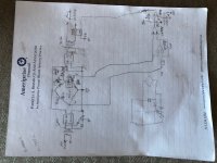
I’ve been thinking about this circuit for several days and decided I should post my thoughts before they become so stale they’re irrelevant. I further apologize for the photo of my working sketch--- I hope it’s decipherable. I’ve run out of procrastination time and must do chores.….
Steve
-----------------------------------------------------------------------------------------------------------------------------------------------------------------------------------------------
I’m intrigued by the notion of temperature regulating a hotwire cutter. This is a project I’m unlikely to implement, but it’s an interesting design challenge, plus I’m practicing procrastination. So some ideas, for what they’re worth (free):
I really like the idea of using the hotwire as both heating element and temperature sensor. From this perspective, steel wire (stainless?) seems attractive since it has a much higher TCR than nichrome (better for temperature sensing), higher resistivity than copper (less current needed to heat), and it’s cheap. There does seem to be a large variation in resistivity among various steel alloys, so stashing replacement wire or a reliable source seems a good precaution. I’m clueless re susceptibility to corrosion among the various metals.
I would make the hotwire one of the resistors in a AC-driven bridge circuit. A rough diagram is below. This circuit is of course this purely conceptual, untested and not simulated; I could have flawed thinking.
Assuming a 5 ohm (room-temp) hotwire per Dave’s opening post, the hotwire leg of the bridge has a 0.5 ohm resistor in its lower arm so that 90% of the applied power goes to the hotwire. The opposite leg of the bridge would include a pot to adjust the setpoint temperature.
Again per the opening post, I’m assuming about a 5 ohm hotwire and a 24 VAC transformer secondary, controlled by a solid-state relay (SSR) with zero-cross triggering as the controlled power source. A full-wave rectifier delivers unfiltered power to the hotwire bridge. Additionally, a 6 VAC transformer with full-wave rectifier also drives the hotwire in diode-OR fashion. Thus the hotwire is driven with 24 VAC during heating, but only 6 VAC when the wire is below setpoint. This arrangement allows the bridge to be monitored continuously; the unfiltered drive allows the SSR to drop out of conduction at zero crossings whenever the SSR is not enabled.
In my imagination at least, the circuit operates as follows:
Note that with the resistor values I’ve sketched and the setpoint wiper at CCW, the bridge would be balanced with the wire at room temp. Also note that as the wire heats, its resistance will rise, causing the bridge voltage at the lower side of the hotwire (W) to decrease with rising temperature.
Assume the circuit is starting with the wire at room temp and the setpoint pot targets an elevated temperature. In this state the wire is cold and the bridge’s W node voltage will be higher than the S node voltage; consequently comparator U1A will be low, discharging C1 to ground, comparator B to ground, in turn energizing the SSR. The wire begins to heat. Eventually, the hotwire temp exceeds the setpoint, the bridge W node voltage falls below the S node voltage; consequently comparator U1A switches high, allowing C1 to charge toward B+, comparator B to switch high, and the SSR switches off. Now the hotwire is driven with only 6 VAC and wire temperature will cool. Now the controller should cycle near the setpoint.
A few notes:
R2 and R3 trim pot are provided to adjust amplifier and comparator offset errors to ensure that the comparators do not trigger into the low state near zero crossings; otherwise, there could be erroneous heating.
The R1, C1 network (~ 15 ms) is intended to capture and hold a request for heating long enough for the next zero-crossing enable of the SSR.
I specified resistor values to help illustrate operating principles. In practice, I think the resistors near the setpoint pot should be revised for a more restricted range of setpoint adjustment to make the pot less “twitchy.”
There’s some chance that the LM358 opamp could be designed out. Higher TCR wire and elevating the 6 VAC transformer to 12 VAC would help in that regard--- but 12 VAC might be too much applied power in the reduced power state. (~ 25% of full power.) Experimentation required.
B+ and ground supply to opamp and comparator not shown.
Suggested SSR with zero-crossing turn on.
Blocked
Attachments
Last edited:
...----------------------------------.........------------------------------------------...{truncated for clarity}
Please don't do that, fill the field with unbroken characters. It really screws-up the rendering in my browser. And adds nothing to your now-hard-to-read message.
- Home
- Design & Build
- Equipment & Tools
- Hot wire cutter circuitry for better speakers?