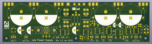
I'm building class-G amplifiers (which I mistakenly labelled as class-H on the silkscreen - sacre-bleau!), which stretches my lab supply capabilities.
Normally I use an pair of old Thurlby PL320 supplies (nominally 0-32V, 0-2A), which I tweaked ages ago to do 0-40V, 0-2A. They don't do enough current to actually start testing amps though, so once I've done the initial setup and smoke testing I generally substitute a +/-40V or +/-56V unregulated supply.
It's not ideal. I'd like a lab supply that's capable of driving a typical 100Wish power amp to the limits of it's capabilities, so something like 60V, 5A.
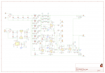
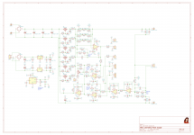
So ages ago, I lashed up the circuit shown. The idea is to use half a dozen N-channel lateral MOSFETs in parallel to do something like 60V, 6A. It never made it past the schematic stage.
Until now, when I need another couple of lab supplies to test my class-G amplifiers.
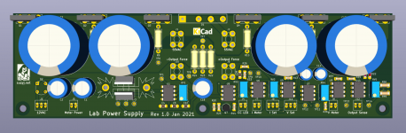
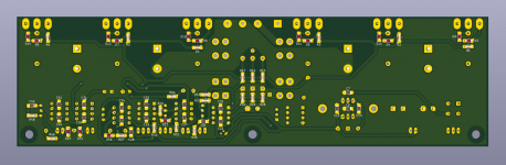
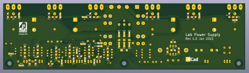
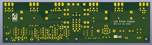
So I've spent the last couple of days doing layout, and come up with a reasonably simple 235mm x 65mm PCB, that has everything bar the transformer (actually 2, as I need a 2x12VAC low current supply to drive this), plus pots and panel meters.
Please see attached LTspice simulation, KiCad schematic, and PCB.
Alas I won't be ordering this PCB for a couple of weeks, as I've spent my play money on amplifier PCBs and I don't want to get into trouble.
Normally I use an pair of old Thurlby PL320 supplies (nominally 0-32V, 0-2A), which I tweaked ages ago to do 0-40V, 0-2A. They don't do enough current to actually start testing amps though, so once I've done the initial setup and smoke testing I generally substitute a +/-40V or +/-56V unregulated supply.
It's not ideal. I'd like a lab supply that's capable of driving a typical 100Wish power amp to the limits of it's capabilities, so something like 60V, 5A.
So ages ago, I lashed up the circuit shown. The idea is to use half a dozen N-channel lateral MOSFETs in parallel to do something like 60V, 6A. It never made it past the schematic stage.
Until now, when I need another couple of lab supplies to test my class-G amplifiers.
So I've spent the last couple of days doing layout, and come up with a reasonably simple 235mm x 65mm PCB, that has everything bar the transformer (actually 2, as I need a 2x12VAC low current supply to drive this), plus pots and panel meters.
Please see attached LTspice simulation, KiCad schematic, and PCB.
Alas I won't be ordering this PCB for a couple of weeks, as I've spent my play money on amplifier PCBs and I don't want to get into trouble.
Attachments
Last edited:
I'm just thinking 'why laterals' with their low transconductance and high on resistance. Such a waste of wonderful audio devices I would have thought for an application like this.
Why not use cheap high power vertical FET's instead?
Sorry that all sounds a bit negative but laterals for a series pass regulator
Why not use cheap high power vertical FET's instead?
Sorry that all sounds a bit negative but laterals for a series pass regulator
Very good point. I designed using laterals mainly just because I have a bunch, and I don't really have any vertical MOSFETs in high dissipation packages (TO-3P, TO-247 etc).
The vertical MOSFETs _are_ rather cheaper - I note I can get 10 off IRFP250s for AU$22, which'll buy maybe 2 ECX10N20s...
I shall model using the vertical FETs, and see if there's any difference.
The vertical MOSFETs _are_ rather cheaper - I note I can get 10 off IRFP250s for AU$22, which'll buy maybe 2 ECX10N20s...
I shall model using the vertical FETs, and see if there's any difference.
It's all relative.
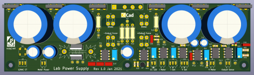
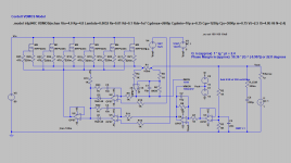
I think the vertical FETs will work quite well. I've incorporated them into the schematic and done a PCB rev to accommodate them (hey it's really only a matter of swapping source and drain). I also changed some of the caps to film ones, in an attempt to offset the cost reduction from ditching the laterals. One of the things that bugs me about my old Thurlby supplies is they wander around a bit as they heat up. I've put a bit of effort into reducing that with this, using low offset opamps, plus a good quality reference to base the whole lot off.
It's a bit more complicated than it needs to be, but that's because I have vague ideas of substituting DACs for the voltage and current set pots and using ADCs in place of the panel meters, so some of the circuitry is really just to get everything neatly referenced to a common point.
I've also spent some time finessing the layout, making sure things are labelled. I've even done designators on the silkscreen, which I usually don't, on account of the board being very relaxed.
I'm becoming quite a KiCad zealot. Like all CAD tools, it takes a while to learn the ropes, and then takes more time to learn the shortcuts and get it set up just the way you like. I still haven't gotten the hang of making 3D models, but otherwise I find it quicker and easier to use than Protel now (which I've used ever since it was Autotrax).
Attachments
-
 Screen Shot 2021-01-10 at 3.26.59 pm.png643.8 KB · Views: 175
 -
 Screen Shot 2021-01-10 at 3.26.23 pm.png568.4 KB · Views: 132
 -
 Screen Shot 2021-01-10 at 3.21.21 pm.png526.6 KB · Views: 148
 -
 Screen Shot 2021-01-10 at 3.20.46 pm.png602.8 KB · Views: 637
 -
 Screen Shot 2021-01-10 at 3.19.53 pm.png952.9 KB · Views: 690
So the laterals get to live for another day for audio  and that board design is looking good.
I wonder if you could economise on all the FET G-S protection... using a single Zener + diode before the FET gate resistors and adding a lowish value resistor from the driving opamp output to just pad it down a little.
and that board design is looking good. I wonder if you could economise on all the FET G-S protection... using a single Zener + diode before the FET gate resistors and adding a lowish value resistor from the driving opamp output to just pad it down a little.
I do not get your preference for VFETs in this application. We are talking about PowerFETs working in their linear region, where VFETs show stability problems. Certainly latFETs are more expensive - but as I understand this is not a commercial project but DIY. So you are free to choose the best solution, not the most economical.
Just my 2 c
Just my 2 c
I’ll be making four of these. That’s 24 FETs. I’m paying for those FETs out of my own pocket. using laterals, that’s about AU$300. Using verticals, about $40. If I could convince myself that the verticals are going to be a problem, I’d stick with laterals, but I can’t. They simulate fine, I can simply throw more source resistance at them if I need to to force them to share current (at 6A, the 220Ω source resistors are dissipating 220mW, so I could easily go to 1Ω or more if I need to), and the current is explicitly servoed, so there’s no issues with thermal runaway etc. They’re fast enough to track line and load transients, and they have ample transconductance, so there are no problems there.
It’s a series regulator, not an amplifier.
It’s a series regulator, not an amplifier.
Hi jackinnj,
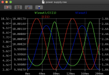
Can you share your simulation? I'm not getting that when I put an AC current source across the output (see attached).
In my test I used a 10Hz, 1A source with a 2A offset, so it varies between 1A and 3A.
I set my output voltage to 10V, and set the current limit to 5A to keep it out of the way. The measured output voltage varies between 9.9987V and 10.0013V, so a ∆V of 2.6mV. ∆I is 2A, so I make output resistance 1.3mΩ.
Simply graphing the absolute output resistance gives something that varies from 3.33 to 10.0Ω, as that's what's needed to put 1 to 3A out at 10V...
I'm not super confident that I'm doing this the right way.
Attachments
Note -- you didn't specify the ESR of the output filter cap -- this is pretty important.
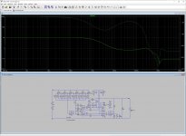
Steve Sandler wrote a paper on the approximation of stability, i.e. phase margin, by looking at the output impedance vs frequency. It's referenced on the PicoTest website , and there's an application note on the Omicron Labs website.
Steve Sandler wrote a paper on the approximation of stability, i.e. phase margin, by looking at the output impedance vs frequency. It's referenced on the PicoTest website , and there's an application note on the Omicron Labs website.
Attachments
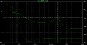
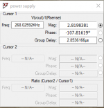
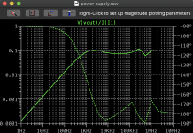
You forgot to turn off the AC stimulus on the Vset node (V3).
The AC analysis confirms my transient analysis.
Yes, silly me
BTW I have the Thurlby PL330 supply. Care to elaborate how you tweaked the PL320 to get +-40V?
- Home
- Design & Build
- Equipment & Tools
- Lab supply using Lateral MOSFETs