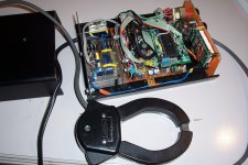
I have finalized the instrument:
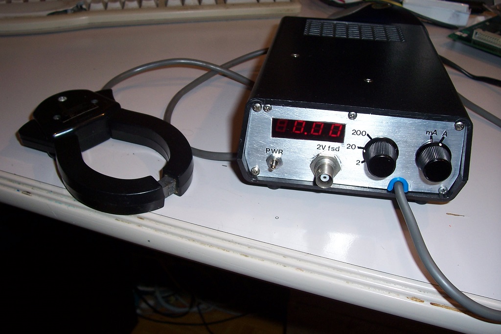
Its main purpose is as a current probe, to visualize or analyze the current waveforms, but I also included a display showing the rms value: it will often be needed, and it is easier than having to connect a rms voltmeter, or asking the oscilloscope to compute the value.
I am going to properly document the project, for altruistic reasons of course, as these probes seem to be widespread among the DIYaudio community, and also for egoistic reasons: when I force myself to make the documentation complete and readable by anyone, it will also be understandable by my later self, in case I need to fix or modify the instrument in the future.
Having it archived on the forum is also a big advantage since my personal archives are a mess of paper and digital files, and retrieving anything is always a daunting task that takes ages. On the forum, I simply have to make a search on my name, with one or two search terms and that's it: much quicker and easier.
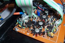
Here is the final circuit:
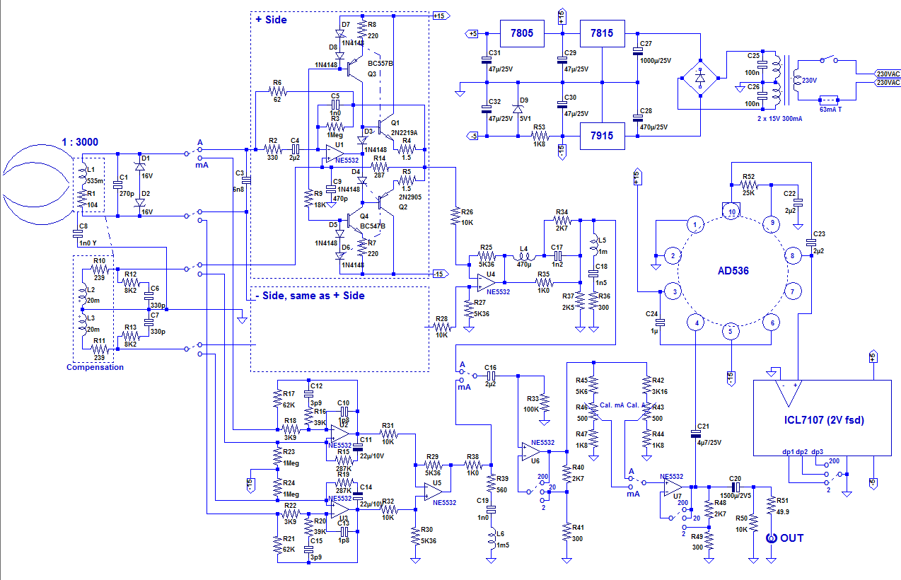
Some comments:
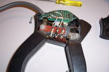
L2 & L3 are the bifilar, aircore compensation windings mounted inside the probe. As they are connected in opposition, their inductances cancel.
They have an odd value because I used an already wound coil-former: this spared me a winding job.
A word about C8. I faced a dilemma: I didn't want to leave the metallic cores floating, because they could pick-up electrostatic interferences and transfer them to the windings covering them, but I didn't want to connect them directly to the GND, as they could come into contact with some live part.
The tradeoff I opted for was to connect them to the GND via a low value, Y-type safety cap.
It is sufficient to shunt HF interference but it does not compromise the safety or the galvanic isolation, something essential for this kind of instrument.
D1 & D2 have no active role, they just protect the windings and electronics in case the probe is subjected to a high current with the power switched off: the zero-field circuitry being inactive, it cannot compensate the primary currents.
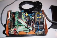
The "Ampere" conditioning circuits have discrete buffers, because they need to cope with the maximum peak of the transformed measured current (200A times √2 times the overload margin, ~2 in this case).
On the "mA" path, the role of R23 & 24 is to "paralyze" the circuit when it is not active.
Initially, C1 was mounted downstream of the mA/switch, and it changed the amplifiers into a multivibrator when the inputs were left open.
As the oscillation was a 10kHz 25Vpp squarewave, it leaked elsewhere in the circuit.
Since all the 6 sections of the switch were already used up, I didn't have the option of shunting the inputs or removing the power to the unused path, which is why I resorted to the resistors.
Under active conditions, they introduce practically no error, and they are sufficient to eliminate unwanted oscillations
Its main purpose is as a current probe, to visualize or analyze the current waveforms, but I also included a display showing the rms value: it will often be needed, and it is easier than having to connect a rms voltmeter, or asking the oscilloscope to compute the value.
I am going to properly document the project, for altruistic reasons of course, as these probes seem to be widespread among the DIYaudio community, and also for egoistic reasons: when I force myself to make the documentation complete and readable by anyone, it will also be understandable by my later self, in case I need to fix or modify the instrument in the future.
Having it archived on the forum is also a big advantage since my personal archives are a mess of paper and digital files, and retrieving anything is always a daunting task that takes ages. On the forum, I simply have to make a search on my name, with one or two search terms and that's it: much quicker and easier.
Here is the final circuit:
Some comments:
L2 & L3 are the bifilar, aircore compensation windings mounted inside the probe. As they are connected in opposition, their inductances cancel.
They have an odd value because I used an already wound coil-former: this spared me a winding job.
A word about C8. I faced a dilemma: I didn't want to leave the metallic cores floating, because they could pick-up electrostatic interferences and transfer them to the windings covering them, but I didn't want to connect them directly to the GND, as they could come into contact with some live part.
The tradeoff I opted for was to connect them to the GND via a low value, Y-type safety cap.
It is sufficient to shunt HF interference but it does not compromise the safety or the galvanic isolation, something essential for this kind of instrument.
D1 & D2 have no active role, they just protect the windings and electronics in case the probe is subjected to a high current with the power switched off: the zero-field circuitry being inactive, it cannot compensate the primary currents.
The "Ampere" conditioning circuits have discrete buffers, because they need to cope with the maximum peak of the transformed measured current (200A times √2 times the overload margin, ~2 in this case).
On the "mA" path, the role of R23 & 24 is to "paralyze" the circuit when it is not active.
Initially, C1 was mounted downstream of the mA/switch, and it changed the amplifiers into a multivibrator when the inputs were left open.
As the oscillation was a 10kHz 25Vpp squarewave, it leaked elsewhere in the circuit.
Since all the 6 sections of the switch were already used up, I didn't have the option of shunting the inputs or removing the power to the unused path, which is why I resorted to the resistors.
Under active conditions, they introduce practically no error, and they are sufficient to eliminate unwanted oscillations
Attachments
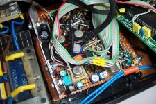
The rest of the circuit is relatively mundane and ordinary: each path goes through an equalizer, aimed at taming the seriously anarchic behavior of the sensor at high frequencies.
Equalization starts at the conditioning amplifiers, but the specific part is downstream: L4, R35, C17, R34,... for the ampere side, and R38, R39, C19, L6 for the mA side.
That is needed to eliminate the ringing.
The supply and AC voltmeter are run-of-the-mill circuits that haven't changed for more than 40 yrs.
They are perfectly OK in this case, no need to reinvent a rounder wheel.
What about the performances? As hinted earlier, the BW is flat from below 2Hz to more than 100kHz, which is perfectly OK for audio work.
The step response is correct, which means some tradeoffs: without this requirement, the BW can be pushed to 250kHz by adapting the EQ circuit, but the transient response becomes ugly.
Some examples:
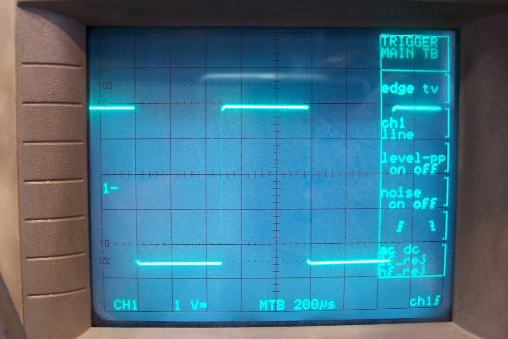
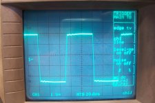
A 10kHz squarewave on the mA path:

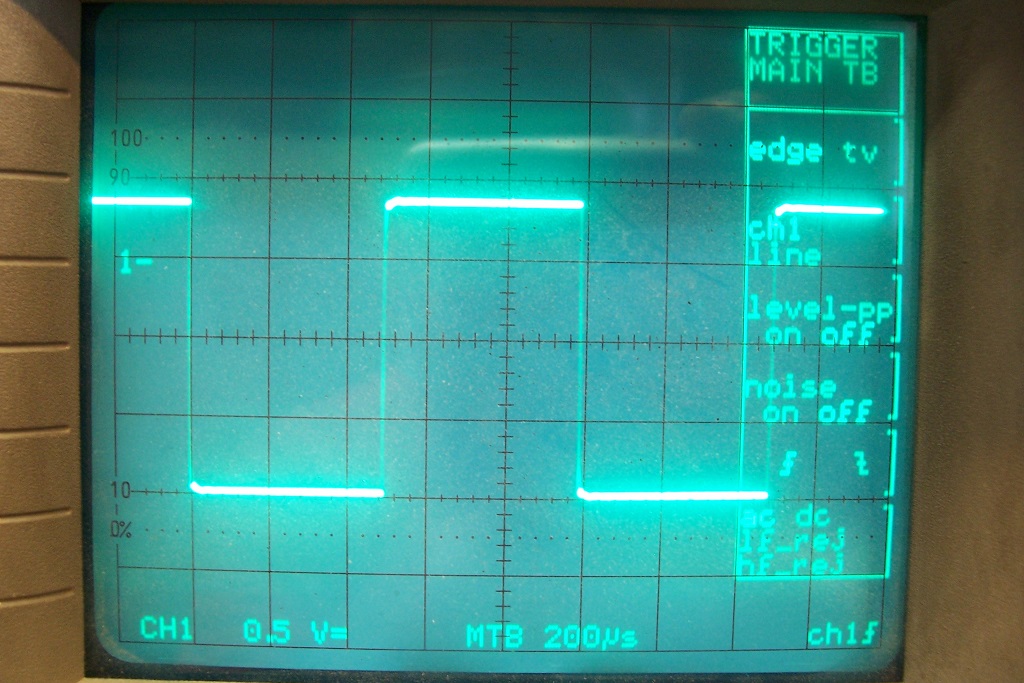
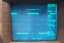
A 1kHz squarewave on the mA path:
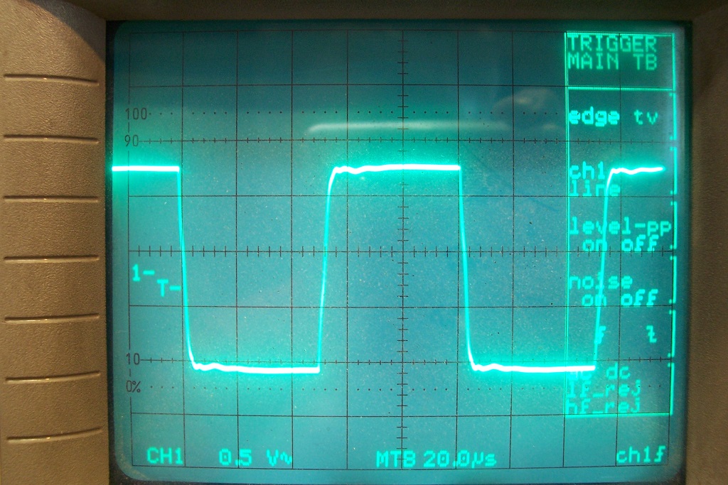
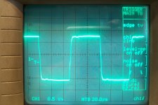
A 10kHz squarewave on the A path:
A 1kHz squarewave on the A path:
The waveforms are far from being perfectly spotless: some ripples and wrinkles remain, and it is possible to refine the equalization to arrive at a perfectly square output, but it makes little sense: the position of the tested conductor inside the magnetic loop has a greater influence.
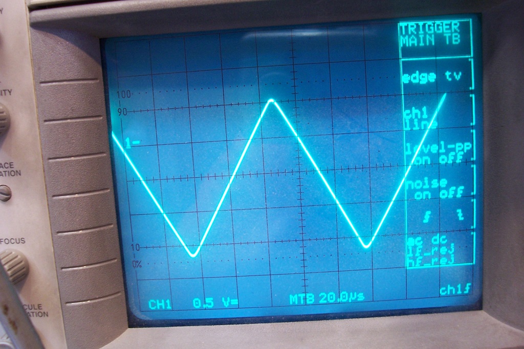
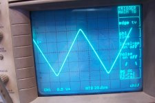
The linearity is excellent, thanks to the zero-field and the negative resistance, unlike traditional magnetic components: here is a 10kHz triangle wave:
What about the sensitivity to external stray fields? That's a thorny issue, because of the shape of the magnetic circuit, its relatively poor quality, and the high sensitivity ranges.
I knew from the start that the 2mA range wouldn't be usable: it came to exist because of the combination of the range and unit selectors, but it has never been planned in its own right.
On my bench (energized), I can reach down to 0.1mA rms if I very carefully orient the probe in 3D to get the smallest reading.
With random orientation, the reading can be anywhere and often exceeds the 2mA full range.
Thus, utterly unusable.
If I move to a quiet environment (my garden), the reading falls between 20 and 50µA, so probably usable except there is nothing to be measured in the garden.
The main source of noise inside is the 50Hz and its harmonics, unsurprisingly.
Outside, the main source is movement and vibration of the probe: the magnetic circuit retains a small residual remanent field biasing the probe and making it work as a seismograph
Equalization starts at the conditioning amplifiers, but the specific part is downstream: L4, R35, C17, R34,... for the ampere side, and R38, R39, C19, L6 for the mA side.
That is needed to eliminate the ringing.
The supply and AC voltmeter are run-of-the-mill circuits that haven't changed for more than 40 yrs.
They are perfectly OK in this case, no need to reinvent a rounder wheel.
What about the performances? As hinted earlier, the BW is flat from below 2Hz to more than 100kHz, which is perfectly OK for audio work.
The step response is correct, which means some tradeoffs: without this requirement, the BW can be pushed to 250kHz by adapting the EQ circuit, but the transient response becomes ugly.
Some examples:
A 10kHz squarewave on the mA path:
A 1kHz squarewave on the mA path:
A 10kHz squarewave on the A path:
A 1kHz squarewave on the A path:
The waveforms are far from being perfectly spotless: some ripples and wrinkles remain, and it is possible to refine the equalization to arrive at a perfectly square output, but it makes little sense: the position of the tested conductor inside the magnetic loop has a greater influence.
The linearity is excellent, thanks to the zero-field and the negative resistance, unlike traditional magnetic components: here is a 10kHz triangle wave:
What about the sensitivity to external stray fields? That's a thorny issue, because of the shape of the magnetic circuit, its relatively poor quality, and the high sensitivity ranges.
I knew from the start that the 2mA range wouldn't be usable: it came to exist because of the combination of the range and unit selectors, but it has never been planned in its own right.
On my bench (energized), I can reach down to 0.1mA rms if I very carefully orient the probe in 3D to get the smallest reading.
With random orientation, the reading can be anywhere and often exceeds the 2mA full range.
Thus, utterly unusable.
If I move to a quiet environment (my garden), the reading falls between 20 and 50µA, so probably usable except there is nothing to be measured in the garden.
The main source of noise inside is the 50Hz and its harmonics, unsurprisingly.
Outside, the main source is movement and vibration of the probe: the magnetic circuit retains a small residual remanent field biasing the probe and making it work as a seismograph
Attachments


One could question the point of the whole project: after all, current probes aren't exactly a rarity, and converting an old electrotechnical instrument into something else looks like a needlessly difficult path.
I had this probe gathering dust in a chest, and converting it into a useful instrument looked like a good idea.
The zero-field, negative-resistance circuit sublimates this low-accuracy, low-linearity, low-sensitivity single-frequency probe into a highly sensitive, highly linear instrument covering the 2Hz-->100kHz range.
Of course, that's what other current probes do, and in general they have a wider bandwidth, but good current probes tend to be short and fat, and have a small opening.
This one has slender jaws and a wide opening, which allows some interesting tricks.
For example, it allows easy hardware arithmetics: suppose you want to measure the shoot-through pulses of a class B OP stage: you just need to pass each emitter connection in phase, and the output in antiphase to directly extract the shoot-through current.
This kind of trick is well-known, and applicable to any other probe, but the wide opening of this one makes things easier.
This trick is more unusual, and is made possible thanks to the wide jaws: hum can have unexpected origins, like induced chassis currents.
Imagine you place a small transformer at one end of a chassis built from metal profiles, and sensitive circuitry at the other end.
You have done your homework, and checked that at such a distance the stray field from the transformer will be harmless.
However, when you make your tests you notice a horrendous hum level.
What's going on?
Here is the answer.
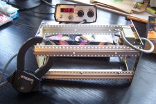
First, the situation with no power applied to the transformer:

Now, the same with the transformer energized:
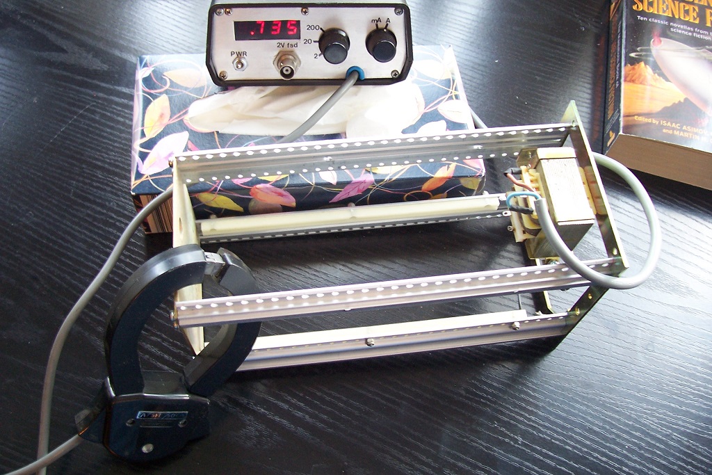
Where does the 735mA come from?
It is induced into the loop formed by the chassis, from the small stray field of the small transformer.
The emf is tiny, but so is is the loop resistance, resulting in a hefty current.
Needless to say that such a current will cause severe hum in anything sensitive, and it can do so at a great distance: the loop transfers the magnetic flux, and it will do so even if the transformer side is magnetically shielded.
Such a probe makes the diagnosing and pinpointing of such problems remarkably easy.
Note that such loops can catch ambient stray fields and concentrate them into the wrong place: if I place my setup example in high ambient stray fields, (with the transformer unpowered), the probe registers a significant current (not 700mA, of course!)
I had this probe gathering dust in a chest, and converting it into a useful instrument looked like a good idea.
The zero-field, negative-resistance circuit sublimates this low-accuracy, low-linearity, low-sensitivity single-frequency probe into a highly sensitive, highly linear instrument covering the 2Hz-->100kHz range.
Of course, that's what other current probes do, and in general they have a wider bandwidth, but good current probes tend to be short and fat, and have a small opening.
This one has slender jaws and a wide opening, which allows some interesting tricks.
For example, it allows easy hardware arithmetics: suppose you want to measure the shoot-through pulses of a class B OP stage: you just need to pass each emitter connection in phase, and the output in antiphase to directly extract the shoot-through current.
This kind of trick is well-known, and applicable to any other probe, but the wide opening of this one makes things easier.
This trick is more unusual, and is made possible thanks to the wide jaws: hum can have unexpected origins, like induced chassis currents.
Imagine you place a small transformer at one end of a chassis built from metal profiles, and sensitive circuitry at the other end.
You have done your homework, and checked that at such a distance the stray field from the transformer will be harmless.
However, when you make your tests you notice a horrendous hum level.
What's going on?
Here is the answer.
First, the situation with no power applied to the transformer:
Now, the same with the transformer energized:
Where does the 735mA come from?
It is induced into the loop formed by the chassis, from the small stray field of the small transformer.
The emf is tiny, but so is is the loop resistance, resulting in a hefty current.
Needless to say that such a current will cause severe hum in anything sensitive, and it can do so at a great distance: the loop transfers the magnetic flux, and it will do so even if the transformer side is magnetically shielded.
Such a probe makes the diagnosing and pinpointing of such problems remarkably easy.
Note that such loops can catch ambient stray fields and concentrate them into the wrong place: if I place my setup example in high ambient stray fields, (with the transformer unpowered), the probe registers a significant current (not 700mA, of course!)
Attachments

- Status
- This old topic is closed. If you want to reopen this topic, contact a moderator using the "Report Post" button.