flashback - Stereo System AB Comparator
Features:


Hi there!
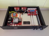
Today I want to share with you my first device design, totally devised and built in 2018.
It is a two-stage AB system comparator controlled by an Atmel uC that allows you to make critical comparison of two power and/or two unbalanced line level devices, either independently or synchronously. Four built-in dummy loads has been placed for the power level stage, making it totally safe for any kind amplifier, either tube or solid state. Finally, a true RMS voltmeter is included, so you can do pre-test level matching on both stages.
After one year of having finished its construction and testing it a lot under different configurations, it seems to me that it is an extremely useful tool, of which there are very few in the market with this level of features and no freely available design for builders, so it seems like a good reason to share it with the great people in this forum, from which I have been learning so much since a few years ago.
I would love to make a second improved version of "flashback", available and accessible to everyone, but I am not an electronics professional, so I think I would need your valuable contributions for make this happen.
Although it works correctly and has proven to be very reliable, there is still plenty of room for improvement. It would be interesting, for example, to have a balanced line level stage or the possibility of doing blind tests (ABX comparator). However, I believe that at this point cost reduction is the key issue that should be addressed with the highest priority, since the total construction cost of this unit far exceeds any commercial viability. The good news is that there is plenty of room for cost savings, either by redesigning or simply selecting components with better cost-benefit ratio.
I hope you get motivated with this project. I firmly believe that every audio fan should have one of these at home.
I have some PCBs left over and they are available in case someone wants to experiment or build their own flashback unit.
DESIGN DESCRIPTION PART I: Power Stage Switching Mechanism
The first design aspect that I would like to detail is the switching mechanism for the power amplification stage. This is probably the most original part of the entire circuit and uses five relay contacts per channel, sequentially triggered by the uC to achieve a Breake-before-make transition, at the same time that the speakers and built-in dummy loads are switched in Make-before-brake mode. This guarantees a secure and smooth transition between A and B systems, without clicks or any other audible artifacts, either for tube or solid state amplifiers. Finally, this configuration allows the device to be operated in reverse, switching between two pairs of speakers instead of two power amplifiers.

The image above shows the circuit design for this stage, which uses 5 DPDT relays: K1, K2, K3, K4 and K5 and where each relay performs the same function for left and right channels at the same time. To facilitate the explanation, I will always refer only to the left channel of the circuit, where the common speaker is observed at the center, routed to amplifiers A and B at the top and bottom respectively.
On the positive rail, a double contact switches the amplifier between the speaker and the dummy load resistor. This configuration is necessary for switching in a make-before-breake mode. On the other hand, the negative rail has a traditional configuration with a single DPDT relay that directly switches both A and B channels.
If you observe the circuit, you will note that the currently active amplifier is B. To switch from system B to system A, the uC must modify the state of the relays in the following five steps sequence:
K1: The first of two contacts is switched. The amplifier B is now connected in parallel with the speaker and the dummy load
K2: Now amplifier B is connected only to the resistor
K3: The negative side of the speaker is disconnected from circuit B and connected to amplifier A, which in turn is connected to the resistor
K4: Now amplifier B is connected to the resistor and the speaker
K5: Finally, the transition is completed by disconnecting the dummy load from circuit A.
A 20 ms delay has been artificially introduced between each step, resulting in an effective transition time of 40 ms. Of course, if we want to switch back to system B, we only need to change the state of the relays using the same sequence in the opposite direction.
Component Selection
K1, K2, K4, K5: Omron MY2N-DC12(S), 5A DC (inductive load: 2A at 220 VAC), 2 bifurcated Ag poles (50 mOhm max), Plug-in Terminals
K3: Omron LY2Z-DC12, 10A DC (inductive load: 4A at 110 VAC), 2 bifurcated Ag poles (50 mOhm max), Plug-in Terminals
These are large ice cube type relays and were meticulously selected to ensure long-term operation. Its plug-in terminals and bifurcated contacts allow to minimize resistance and increases reliability.
Dummy Load Resistors: 4x Arcol/Ohmite AP101 8R2 J, 8.2 Ohms, ThickFilm, 100 Watt resistor.
These resistors are very expensive, but use very little space per Watt compared to other technologies. I installed them with a small heatsink on each pair and I have never felt them even get warm. Probably using 100W DC resistors is oversized for the application, so here is a good opportunity to reduce costs without major commitments, apart from the volume inside the chassis.
Finally, large jumpers have been added to the PCB so that the dummy resistors can be disconnected if required, allowing higher powers or even connecting another pair of speakers instead.
That's all for now. I would be very grateful if you let me know your thoughts on this design. If there is enough interest I promise to go detailing and publishing more info about this design.
Features:
- Microcontroller driven two stage relay switching system
- Allows you to make critical comparison of two power and line level systems in a seamlessly way
- Compare both stages simultaneously or independently
- both stage reversible
- Power stage designed for up to 100 Watts, with safe five-step sequential switching mechanism
- Safe for tube amplifiers, includes four detachable 8 Ohms, 100 Watts dummy load resistors
- True RMS voltmeter for pre-test level adjustment
- 100% passive system. Only relay contacts in the signal path
- Programmable IR remote control receiver (works with any already available remote controller)
- Firmware upgradeable
Hi there!
Today I want to share with you my first device design, totally devised and built in 2018.
It is a two-stage AB system comparator controlled by an Atmel uC that allows you to make critical comparison of two power and/or two unbalanced line level devices, either independently or synchronously. Four built-in dummy loads has been placed for the power level stage, making it totally safe for any kind amplifier, either tube or solid state. Finally, a true RMS voltmeter is included, so you can do pre-test level matching on both stages.
After one year of having finished its construction and testing it a lot under different configurations, it seems to me that it is an extremely useful tool, of which there are very few in the market with this level of features and no freely available design for builders, so it seems like a good reason to share it with the great people in this forum, from which I have been learning so much since a few years ago.
I would love to make a second improved version of "flashback", available and accessible to everyone, but I am not an electronics professional, so I think I would need your valuable contributions for make this happen.
Although it works correctly and has proven to be very reliable, there is still plenty of room for improvement. It would be interesting, for example, to have a balanced line level stage or the possibility of doing blind tests (ABX comparator). However, I believe that at this point cost reduction is the key issue that should be addressed with the highest priority, since the total construction cost of this unit far exceeds any commercial viability. The good news is that there is plenty of room for cost savings, either by redesigning or simply selecting components with better cost-benefit ratio.
I hope you get motivated with this project. I firmly believe that every audio fan should have one of these at home.
I have some PCBs left over and they are available in case someone wants to experiment or build their own flashback unit.
DESIGN DESCRIPTION PART I: Power Stage Switching Mechanism
The first design aspect that I would like to detail is the switching mechanism for the power amplification stage. This is probably the most original part of the entire circuit and uses five relay contacts per channel, sequentially triggered by the uC to achieve a Breake-before-make transition, at the same time that the speakers and built-in dummy loads are switched in Make-before-brake mode. This guarantees a secure and smooth transition between A and B systems, without clicks or any other audible artifacts, either for tube or solid state amplifiers. Finally, this configuration allows the device to be operated in reverse, switching between two pairs of speakers instead of two power amplifiers.
The image above shows the circuit design for this stage, which uses 5 DPDT relays: K1, K2, K3, K4 and K5 and where each relay performs the same function for left and right channels at the same time. To facilitate the explanation, I will always refer only to the left channel of the circuit, where the common speaker is observed at the center, routed to amplifiers A and B at the top and bottom respectively.
On the positive rail, a double contact switches the amplifier between the speaker and the dummy load resistor. This configuration is necessary for switching in a make-before-breake mode. On the other hand, the negative rail has a traditional configuration with a single DPDT relay that directly switches both A and B channels.
If you observe the circuit, you will note that the currently active amplifier is B. To switch from system B to system A, the uC must modify the state of the relays in the following five steps sequence:
K1: The first of two contacts is switched. The amplifier B is now connected in parallel with the speaker and the dummy load
K2: Now amplifier B is connected only to the resistor
K3: The negative side of the speaker is disconnected from circuit B and connected to amplifier A, which in turn is connected to the resistor
K4: Now amplifier B is connected to the resistor and the speaker
K5: Finally, the transition is completed by disconnecting the dummy load from circuit A.
A 20 ms delay has been artificially introduced between each step, resulting in an effective transition time of 40 ms. Of course, if we want to switch back to system B, we only need to change the state of the relays using the same sequence in the opposite direction.
Component Selection
K1, K2, K4, K5: Omron MY2N-DC12(S), 5A DC (inductive load: 2A at 220 VAC), 2 bifurcated Ag poles (50 mOhm max), Plug-in Terminals
K3: Omron LY2Z-DC12, 10A DC (inductive load: 4A at 110 VAC), 2 bifurcated Ag poles (50 mOhm max), Plug-in Terminals
These are large ice cube type relays and were meticulously selected to ensure long-term operation. Its plug-in terminals and bifurcated contacts allow to minimize resistance and increases reliability.
Dummy Load Resistors: 4x Arcol/Ohmite AP101 8R2 J, 8.2 Ohms, ThickFilm, 100 Watt resistor.
These resistors are very expensive, but use very little space per Watt compared to other technologies. I installed them with a small heatsink on each pair and I have never felt them even get warm. Probably using 100W DC resistors is oversized for the application, so here is a good opportunity to reduce costs without major commitments, apart from the volume inside the chassis.
Finally, large jumpers have been added to the PCB so that the dummy resistors can be disconnected if required, allowing higher powers or even connecting another pair of speakers instead.
That's all for now. I would be very grateful if you let me know your thoughts on this design. If there is enough interest I promise to go detailing and publishing more info about this design.
Whoops, indicator lights on the front telling you which channel is which. And large audible relays clicking. Hmm. Very nice build but I'm wondering what purpose it can really serve?
I'd suggest thinking about the modifications needed to allow this to be used, under computer control, to do double-blind comparison testing.
To my mind its really useful for such a device to have a blind mode where nothing gives away the current setting and any clicks it produces when switching A->B, B->A, A->A and B->B are completely indistiguishable (really hard to do with mechanical relays BTW).
At the very least an ABX should be added - with the X setting hidden from view.
Remember confirmation and expectation biases are _very_ powerful effects (even if you
know about them). Witness the McGurk effect for instance.
This is my true ABX comparator.
AB-BOX : The ABX Comparator - Google Photos
I use dummy relays when switching A->A or B->B
AB-BOX : The ABX Comparator - Google Photos
I use dummy relays when switching A->A or B->B
Attachments
Thank you very much for the feedback received so far. The main idea of this publication is to collect impressions and suggestions for an improved version 2, so I really appreciate all kinds of contributions.
I clearly underestimated the collective desire for an ABX mode, but I think it would be relatively easy to implement by firmware update. Both, the four status LEDs and the relays are independently controlled by an ATtiny88 chip, so anyone who has played with an arduino could find their best way to implement the blind mode.
It is true that relays are pretty noisy and that the click they make when opening sounds different from the closing click, but there are also independent double relay contacts on one side of the circuit, so one of them could be used to generate fake clicks and always obtain the same audible sequence for a true ABX test.
I will dedicate the second part of the Circuit Description to make a general explanation of the circuit, so you can better appreciate the flexibility and potential of this comparator. Maybe I should have started there from the beginning.
Anyway, I personally do not agree with the idea that a comparator without blind test mode is useless, especially when the systems under test are easily differentiable (a modern SS amplifier Vs a SET amplifier for instance). When you do an AB test under the traditional method (listen to A - reconnect - listen to B) you can get a rough idea of the most obvious differences, however, this comparison is severely biased by our auditory memory and its low ability to maintain more subtle details. I don't want to bore you with this matter of auditory memory, but the point is that the quality, detail and reliability of the comparison greatly improves when you can compare two systems directly, without long interruptions. It is also the reason for naming this device flashback, as a form of cure that allows you to make critical comparisons based on your ears, not on the capacity of auditory memory.
That said, I recognize that an ABX mode could also be helpful for more rigorous testing. In fact, several times I found myself doing a simple trick to do blind tests with flashback. The trick is to close your eyes or cover the LED indicators and press the trigger several times on the remote control until you lose track of what the current system was. This method works, but I understand that it is not what most people expect from a system with real ABX capability so in the next iteration of this design I will consider the blind mode from the beginning.
Finally, thanks to LKA for sharing your own ABX comparator design, it looks great, although it seems to me that there is a different design philosophy behind, since one of my goals was to create a completely passive comparator, without active components in the signal path. Anyway, it is good to know that there are more people trying to generate a good comparator and that I am not alone in this world.
- Status
- This old topic is closed. If you want to reopen this topic, contact a moderator using the "Report Post" button.