I am interested in making an AC Millivolt Meter. Something along the lines of a HP (403?). This post is my attempt to judge what level of interest there is for such a project. If there was a kit available with a target of $100 max would this be worthwhile to you? I intend to make it but would like to know about others. Thanks
Hello, I think that you would precise a little bit what would be the milli-voltmeter. What specs are targeted ? - Bandwidth, accuracy, measurement range, etc... What output form ? (LCD display ? analog output ? galvanometer ?...) I think depending on these choice, that could interest lot of people here. Regards. Frex
The HP403b was quite a nice instrument - used positive feedback for very high input impedance - i have one in which i used a Linear Tech true RMS chip development board with a jfet front end. You could use Scott’s single supply A=1,000 amplifier , true Rms chip and the original HP meter.
I did leave out a lot of detail. This would be an Analog meter, true RMS. Right now I am trying to find a source for a suitable movement with about 114mm (4.5") face. Input range of 0.01 - 300 volt in a 1,3,1 sequence. My interest is in audio so I do not expect to have a wide bandwidth, maybe 100kHz top end. Input impedance of 1meg or less. I cannot make any claims on accuracy as of yet, that would have to come later. Thanks for your input.Hello, I think that you would precise a little bit what would be the milli-voltmeter. What specs are targeted ? - Bandwidth, accuracy, measurement range, etc... What output form ? (LCD display ? analog output ? galvanometer ?...) I think depending on these choice, that could interest lot of people here. Regards. Frex
IMHO
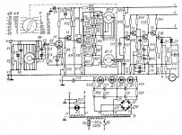
The most optimal is a combination of a vacuum tube at the inlet and a high-voltage OP amp in the amplifier-detector. Cascades are connected by a common feedback for linearity. The tube is more protected from measurement errors.
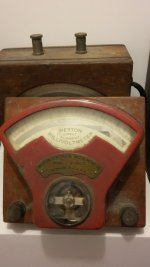
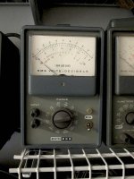
Scheme of the ancient millivoltmeter. Kill this voltmeter is almost impossible.
Operating range up to 5 MHz.
The most optimal is a combination of a vacuum tube at the inlet and a high-voltage OP amp in the amplifier-detector. Cascades are connected by a common feedback for linearity. The tube is more protected from measurement errors.
Scheme of the ancient millivoltmeter. Kill this voltmeter is almost impossible.
Operating range up to 5 MHz.
Attachments
Last edited:
ESP is a good resource. I tend to stay away from battery operated equipment if possible. The 50uA movement limits this to fairly small meters. Also the high Z attenuator looks to be a big hurdle.
I have not seen these available. Do you have any links you could share?You can purchase a good 403 carcase with meter and switch system for $50 or so. This is a huge deal given the quality.
I have not seen these available. Do you have any links you could share?
HP Hewlett Packard Model 403B True RMS AC Voltmeter 1mV-300V USA | eBay
IMHO
The most optimal is a combination of a vacuum tube at the inlet and a high-voltage OP amp in the amplifier-detector. Cascades are connected by a common feedback for linearity. The tube is more protected from measurement errors.
Scheme of the ancient millivoltmeter. Kill this voltmeter is almost impossible.
Operating range up to 5 MHz.
There's enough parts in there for 5 meters. Or a nuclear power plant ;-)
Jan
All transistors can be replaced with one high voltage operational amplifier. Then there will be two elements, a tube and an opaamp.There's enough parts in there for 5 meters. Or a nuclear power plant ;-)
Jan
And a greater tolerance of operator error
To kill the transistor at the entrance, you need only one error. That would kill the tube, you need a strong desire and the time.
Last edited:
I am interested in making an AC Millivolt Meter. Something along the lines of a HP (403?). This post is my attempt to judge what level of interest there is for such a project. If there was a kit available with a target of $100 max would this be worthwhile to you? I intend to make it but would like to know about others. Thanks
Have the 400F down to 0.1mV (-80dB) with 100Khz Filter and would not miss to measure tube power amp's (mono with 4 * KT120) idle noise..

Some prefer full log scales..
Hp
Lookin for sources
In my search for meters I find there are limited choices. One that is nearly ideal is made by a company that does not want to respond to inquiries. I wonder how they are still in business.
Another supplier can provide a movement with a 70mm pointer, no scale, no case. The downside is that the pointer is round.
Readily available 44C2 may be the one to go with, not great as it has a pointer that is about 47mm but it is available at a reasonable price.
Basic Concept
Here the general concept of the project is attached. I am not calling out the specific components as some of them are yet to be determined.
Not shown is the generous use of TVS diodes (Transient-voltage-suppression diode - Wikipedia). There will be one placed on every connection to/from the board. Trying to make this as bullet proof as possible.
The attenuators and the gain block are controlled through reed relays. This is fairly straightforward and allows me to experiment with a rotary selector switch or use a push button range selection. There is no plan to have auto ranging.
Most components are through hole. Some things are only available in SMD.
The power supply will be +5V/-5V derived from a wall wart.
The prototype board designs are near completion and should go out to manufacture in the next few weeks.
Attachments
- Status
- This old topic is closed. If you want to reopen this topic, contact a moderator using the "Report Post" button.
- Home
- Design & Build
- Equipment & Tools
- AC Millivolt Meter