Here is another diy millivolt meter
Millivolt Meter - Barbouri’s Electronics Projects
The milliohm meter looks interesting too.
Milliohm Meter Version 1.5 - Barbouri’s Electronics Projects
Millivolt Meter - Barbouri’s Electronics Projects
The milliohm meter looks interesting too.
Milliohm Meter Version 1.5 - Barbouri’s Electronics Projects
project update
There has been some progress on the meter project. The initial build was less than hoped for. The attenuators were not close enough for my purposes. 1% resistors did not do the job. The frequency response was beginning to roll off at about 200kHz, the target was 800kHz.
There were lessons learned and they will be applied in the next try.
1) Place components as close as possible, reducing trace lengths and capacitance.
2) SMD components should be on the back side of the board. One exception is the optional LEDs.
3) Ground plane on the back side of the board, no plane on the front side.
4) Increase clearance on the ground plane.
Attached you will find the schematics for the next iteration.
I purchased the pcb(s) from JLCPCB.com. They provide very low cost and the turn around time is short. The quality appears to be very good.
If there are any questions or comments feel free to share.
Thanks, Dennis
Attachments
For info, there's another DIY option out there:
Digital Audio Millivoltmeter - Silicon Chip
Not quite the precision piece that Dennis is going for but still potentially useful.
Digital Audio Millivoltmeter - Silicon Chip
Not quite the precision piece that Dennis is going for but still potentially useful.
Progress
This meter project has been a challenge and that is a good thing. The latest version of the boards work well.
I have abandoned the true RMS detector as it is 1) limited bandwidth for the entry level device, 2) terribly small smd package. I have another meter rectifier based on a full wave rectifier and an op amp which looks pretty good. Responsive from about 20 hZ to well over 1 mHz.
After working on the primary attenuator this seems to function quite well, fairly wide bandwidth, I expect to get it to 1 mHz.
The gain blocks are working well, straight out of the book Analog Inc design.
While there are several items to be completed I am pleased with what I have working now.
Is it me or do projects seem to always spawn another project? I am now building a 0-69dB attenuator for the purpose of testing the meter. Also I think it would extremely useful to have some way of automating the performance curves so now I am looking into DDS sweep generator and data aquisition maybe a 4 channel device.
I have tried several times to look at projects from Silicon Chips, they seem to have very interesting projects. So far I have not been able to get to any of them. I am not interested in paying their subscription rates.
I'm not a subscriber.
I pick and choose projects to suit my needs, so I'll get a board and the accompanying issue as I go. Works for me. Also helps being in the same country as the publisher.
There's a whole bunch of issues over at archive.org, from about 2005 - 2010. You might find some stuff in there interesting.
Thank you for the information. I will check it out.
Give this a go:
Silicon Chip Magazine 2009 03 Mar : Free Download, Borrow, and Streaming : Internet Archive
There has been some progress on the meter project. The initial build was less than hoped for. The attenuators were not close enough for my purposes. 1% resistors did not do the job. The frequency response was beginning to roll off at about 200kHz, the target was 800kHz.
is
Is there a specific reason you used the LT1252 CFB opamp in this application?
You must load a CFB opamp for it two work properly. The RLoad values for Av=1, 10 are given in the datasheet as well as optimal values for Rf and Rg.
For a gain of 1,000 -3dB should be ~6.4MHz.
You should consider filtering the output as there will be a lot of RFI pickup over a few hundred kHz.
The reason that the LT1252 was used is simply a cost savings. I am using the gain block as described in Linear Tech. AN-106, page 7, where the original was using LT1227 CFB.
Per Mouser the LT1227 is $5.81 vs the LT1252 cost of $4.13. That being said, there may be justification for going back to the LT1227 but until I see a good reason for it the LT1252, and if possible the LM7171 with a cost of $3.21 may be used.
Of course if someone wanted they could readily use the LT1227.
This is all experimental (to me).
Hi Dennis,
Since you're already having success (yay!), maybe these observations are too late.
The TVS parts are not without a performance penalty -- very high capacitance! For 2 Vp-p signals straddling the other terminal of the SMA6J5.0 (Ground in your case), it is upwards of 1400 pF. And it is highly non-linear: For larger signals capacitance drops almost 30% as the instantaneous voltage approaches the clamp rating (read 'non-linear distortion'). Better to leave them all out and trust a pair of Schottky's from U3's input to either rail.
Then I would sure like to talk you out of the choice of a 250+ MHz video amp for this project. That is one serious little amp -- way over-spec'd for signals of a few hundred kHz. It would pose a worthy challenge for an experienced designer, but a VERY tall challenge for a novice.
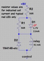
The TO-92 78L05's are great for powering the IC's -- not so much things like LED's and relays. If you're sure you want to keep the LED's, you could power them in series with the relays straight from the 9V. (see thumbnail)
D15 and D16 should probably be omitted; they aren't hurting anything, but they aren't doing any good either. D5 and D6 are worth keeping but I suggest that you change them from the bidirectional ones specified, to the unidirectional device. That way it can give polarity protection, too. Just omit the 'C' from the suffix: SMA6J10CA becomes SMA6J10A. Then double-check the polarity when you fit them.
C4 has to go. Between it and the TVS's, measuring anything over a few kHz would be unlikely. Plus the attenuation would change not just over frequency, but arbitrarily with the 0, -20, -40 dB attenuator setting, too.
The abundance of trimpots will cause errors over temperature. Decent metal-film 1% resistors should be plenty accurate. Remember how small 1% is compared to deciBels -- the signals we're usually measuring.
Cheers
Rick
Since you're already having success (yay!), maybe these observations are too late.
The TVS parts are not without a performance penalty -- very high capacitance! For 2 Vp-p signals straddling the other terminal of the SMA6J5.0 (Ground in your case), it is upwards of 1400 pF. And it is highly non-linear: For larger signals capacitance drops almost 30% as the instantaneous voltage approaches the clamp rating (read 'non-linear distortion'). Better to leave them all out and trust a pair of Schottky's from U3's input to either rail.
Then I would sure like to talk you out of the choice of a 250+ MHz video amp for this project. That is one serious little amp -- way over-spec'd for signals of a few hundred kHz. It would pose a worthy challenge for an experienced designer, but a VERY tall challenge for a novice.
The TO-92 78L05's are great for powering the IC's -- not so much things like LED's and relays. If you're sure you want to keep the LED's, you could power them in series with the relays straight from the 9V. (see thumbnail)
D15 and D16 should probably be omitted; they aren't hurting anything, but they aren't doing any good either. D5 and D6 are worth keeping but I suggest that you change them from the bidirectional ones specified, to the unidirectional device. That way it can give polarity protection, too. Just omit the 'C' from the suffix: SMA6J10CA becomes SMA6J10A. Then double-check the polarity when you fit them.
C4 has to go. Between it and the TVS's, measuring anything over a few kHz would be unlikely. Plus the attenuation would change not just over frequency, but arbitrarily with the 0, -20, -40 dB attenuator setting, too.
The abundance of trimpots will cause errors over temperature. Decent metal-film 1% resistors should be plenty accurate. Remember how small 1% is compared to deciBels -- the signals we're usually measuring.
Cheers
Rick
Attachments
Rick, I will try to be brief.
Nothing about this project is set in stone so any suggested changes are welcome.
TVS diodes- I have been thinking about eliminating them, I do not have them in my prototype, just too lazy to solder them in.
OP amp- I understand your concerns, I chose this to keep as close to the original Linear Technologies design as I could. There are other devices that I am looking at that should reduce the cost and attain the desired performance.
relays and leds- the leds were in there primarily for testing and are optional. The suggestion you have posted is certainly worth looking into.
The attenuator trim pots are totally optional, they are in this layout for my experimentation. It is easier to allow for them and not need them than to need them and not allow for them.
Thank you for the advice. I appreciate your taking the time and effort to contribute.
Dennis
Also, is it supposed to indicate RMS values? If so, to what accuracy at what crest factor?
What are we measuring? Ordinary audio or random waveforms?
Sines, even with 20% THD, read fine on Average.
Random noise is more complicated, but for most audio purposes an Average is fine.
Speech/music even more complicated, but the real problems are time-constants. Do you want to know about 10uS peaks? Can you ignore 10mS peaks? (Most listeners won't notice a few mS of clipping.) Do you want to see inter-syllabic dips or focus on the loud parts?
I have here a SPL meter with log output and it clearly falls short for low input at high frequency.
...You must load a CFB opamp for it two work properly. The RLoad values for Av=1, 10 are given in the datasheet as well as optimal values for Rf and Rg..... consider filtering the output as there will be a lot of RFI ...
A CFB typically does not "need a load". It needs a close pick of the NFB values because these interact with compensation. However the values planned seem to fit the gV=10 case fine (750&83 is near-enough the 1k "load" already). The gV=100 scheme is off the datasheet but unlikely to be a problem.
Agree that a 6MHz-60MHz gain-stage seems excessive for "audio". And unlike a conventional opamp, you can't slug a capacitor across the NFB to form a low-pass. For gV=10, a cheap TL07x opamp covers the audio band; both halves of a TL072 gives gV=100 at less price than a CFB chip. There are better choices of course.
Couldn't we avoid the Unity Gain requirement (per gain stage) by using a slightly more expensive Form C relay, albeit at somewhat lower reliability?
Would probably need somebody sharper than me to figure out how to avoid over-driving the bypassed stage. But practically all the high speed opamps, CFB or otherwise, I've worked with absolutely HATED being lashed down to Unity gain -- unless that was the ONLY gain being asked of them.
Good points on the 'what are we measuring' -- I'd like to know, too.
Interesting input, thanks.
What are we measuring? 20hz to 1mhz, RMS. The meter is to measure the response of a device under test weather that be an amplifier, receiver or a generator, filter ........... So I would say that random signals are not the intended observation target.
In getting this started I followed designs presented by Linear Technologies. There is no reason that things cannot morph from there.
Maybe my goal/perspective is different than others. I am interested in making a useful test instrument and learning about op amps, this could be a basic step towards a larger goal of making an audio bench test set.
One goal is to have an analog meter that I would like to use rather than a digital meter that I would rather not use.
That is one option. What is not shown is that there is allowance for a fuse between the attenuator and U1. I want the fuse (1/16 amp) to open as quickly as possible. I have some concern about the diodes following R1 creating an unintended RC network. Of course the layout could allow for either arrangement.
Yes, you are right about RC-node, we have to concern about it, they (diodes) have to be low-capacitance type (before R, or after). There are "low capacitance small signal schottky diode" type, for example, BAT41 series, (BAT41SWFILM), ets.That is one option. What is not shown is that there is allowance for a fuse between the attenuator and U1. I want the fuse (1/16 amp) to open as quickly as possible. I have some concern about the diodes following R1 creating an unintended RC network. Of course the layout could allow for either arrangement.
I'm not sure it must be shottky. If not, then something like BAV99 what you need.
I think it is better to worry about a device under test, then about your meter input, so I'll better place diodes after R1 - it is much more safe/reliable. I think it's an industry standart. Of cause, R1 have to be powerfull enough type, with power rating >= 0,5 W, or even >=1.0 W.
RC-constant, for example, for 5pF and 1kOhm is 5e-9 - it is almost 32 MHz width. Isn't it ok?
Why fuse? May be just poly-switch?
Last edited:
- Status
- This old topic is closed. If you want to reopen this topic, contact a moderator using the "Report Post" button.
- Home
- Design & Build
- Equipment & Tools
- AC Millivolt Meter