There are a lot of materials available for building speaker enclosures and methods for damping the panels. Good techniques for testing the results along the way seem to be limited. Rather than measure the finished enclosure I've chosen to start by measuring the materials in a standardized way to sort things out in the early stages.
My simplistic approach at this point is to decide on a first approximation of the size and shape of the box I want to build. The drivers won't be a consideration at this point.
To further simply things I'll consider the enclosure's largest panel as being the most likely offender of extraneous and undesirable vibrations. This will reduce the earliest testing to the choice of structural material and methods of damping.
To make the actual measurements I have a methodology choice between microphones and accelerometers. Since the goal is to measure the structural material and the means of damping unwanted vibration I'll start with the accelerometer method. This way any room effects can be reduced to minimal values.
This single panel method can start with the panel in a free-free testing condition by vertical suspension or horizontal soft egg crate foam. I'll probably try each one since either one is easy to accomplish, though I would prefer the foam if the results are acceptable.
In an effort to keep the initial testing simple I'll use a smallish accelerometer and an instrumented impact hammer. The signals from these transducers will go into an oscilloscope for evaluation. The signal amplitudes can then be transferred to most any simple spreadsheet for further evaluation if desired. These measurements can be made with much more sophisticated software, but the front-end hardware would still be about the same with any simple modal analysis system. My goal at this point is to keep these tests and measurements approachable for any real players in the speaker building hobby.
Since I've chosen the accelerometer and hammer method over the microphone approach, I'll now have to design and build the accelerometer and hammer. The easy way out would be to just go buy the instruments. Of course I could just go buy some finished speakers, too. But my curse is that I'm a hardcore DIY kind of guy!
If there's any interest in how this all unravels I'll post progress reports.
Trobbins - Thank you for the REW recommendation. The mma7361L is certainly an inexpensive device and might be satisfactory for this type of measurement. My approach at the moment is to use a more traditional path by building a conventional piezoelectric accelerometer that will require no power supply and can be run straight into a scope channel. The hammer will include a conventional piezoelectric force transducer which can also be run directly into a scope channel. The REW's waterfall display should be an interesting way to look at the impulse signals.
Demian - Thank you for the reply. I agree with you about the unconstrained boundary conditions altering the modes. My first attempts at measuring the panels will be exploratory and an easy free-free setup should be instructive and reproducible on some level. Using a roving hammer and accelerometer test will give me mode amplitudes and frequencies that could be useful for evaluating different damping materials.
This boondoggle's objective right now is primarily an excuse to test the hammer/accelerometer design project. The thought at the moment is that this may lead to a useful way to evaluate speaker building materials. Refinements can be applied as things progress.
Yes the limited bandwidth of the MMA7361L would likely not be high enough with common box panel modal frequencies. The FXLN837XQ has a response to 2.7kHz, which may be sufficient if you can't easily couple a piezo to a soundcard due to impedance loading (although a 100:1 probe may present a suitably high loading, and still keep any signal above the noise floor with a good soundcard).
I haven't used the REW waterfall function yet. The help page indicates the ability to import a captured audio file, which I expect would be the impulse response from your hammer, if it can be captured and recorded and transferred in to REW with sufficient SNR. The alternative is I expect to use a speaker in the box, and driven by REW.
I haven't used the REW waterfall function yet. The help page indicates the ability to import a captured audio file, which I expect would be the impulse response from your hammer, if it can be captured and recorded and transferred in to REW with sufficient SNR. The alternative is I expect to use a speaker in the box, and driven by REW.
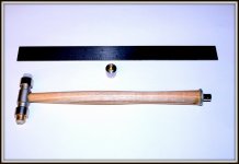
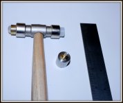
T - Thank you for your continued interest in the project. I've included a couple of photos so that you can see where I am with things, build wise, concerning the transducers. I'll get some DSO screen shots of the signals and post them.
The hammer at this point is a modified jeweler's hammer. They are inexpensive and can be easily machined to do my bidding. The DIY force transducer is installed into one end of the drilled out hammer's head and a shielded cable is routed down the drilled out handle. A BNC connector is then soldered to the cable and epoxied into the base of the handle.
The BNC connector is then tested with a General Radio Megohmmeter for a resistance of > 2G ohms @ 100V. This assures me that there is no meaningful burden on the transducer before it goes to the DSO input or a preamp if one is used.
The DIY accelerometer is built into a piece drilled out 12L14 steel. The electrical feed thru is a Microdot L5 connector. This transducer gets the same resistance test as the hammer.
As far as what to do with the signals after the DSO measurements, I'll try the software you recommended and use the waterfall display to evaluate any damping material. The hammer has a selection of different tips with different stiffness and compliance values. The brass tips are stiff compared to the Nylon tips. Therefor the impulses produced on impact will vary in amplitude and frequency.
Right now I'm experimenting with attaching assorted durometer tips on the brass head. These sticky tips come from the hardware store and are meant for attaching to cabinet doors and such to quiet their closing. There are many to choose from and they each have a different, very repeatable, effect on the impulse spectrum and amplitude generated by the hammer.
This all means that the hammer will act as a proxy driver to excite the panel without having to build the actual box. The panel then responds to the impulse energy spectrum and generates it's own resonance response, transduced by the accelerometer, that can then be displayed in the waterfall.
If any of this is unclear or I'm missing anything in the overall scheme of things so far please warn me!
Attachments
Me caveman.
For many moons, I thump panels with knuckles. Or round rock.
Good thud, make drum. Dead thud, make speaker-box.
Seriously: you collect all this data, and what does it mean? Is F=200 Q=3 better than F=300 Q=2? Is a point-source knuckle (or jewelers hammer) truly the same as a distributed pressure? (If so, why do drummers have pointed sticks and fat sticks and felt beaters?)
George, would you mind elaborating on if the hammer is your step input, or is that provided by a transducer in the hammer (and is it in the hammer so that the step input can then be modified by mechanical interface compliance).
And how and where is the response pickup going to be attached to the panel under test.
Just a bit uncertain")
And how and where is the response pickup going to be attached to the panel under test.
Just a bit uncertain
Wow - super interesting. Those WAVs are worth listening to, very impressive differences between the materials.
The hammer that I've designed is intended to generate a half sine impulse. The frequency content and amplitude of the impulse can be adjusted to fit the test requirements. The explanation of it's design and applications can found with a Google search for "modal hammer". If you click on "images" there will be lots of information that should answer most of your questions. Designing and building an accelerometer follows along the same path.
My interest at the moment is to evaluate the properties of various damping materials that can be used to control resonances in speaker enclosures. These tests can be further expanded to evaluate bracing techniques when I get to that part. My approach is to strip the testing down to it's lowest common denominators. To begin with those would be the panel material and the damping material. This is obviously not a novel undertaking as many have done the same thing.
I enjoy doing the testing and measuring exercises and developing the requisite instruments along the way. Modal analysis is probably the best and most complete method of arriving at my end goal, but the available instrumentation and software to accomplish the task using this method are generally quite expensive.
Having a machine shop in the garage and a couple of benches to set up experiments on in the house encompass my favorite form of recreation. If I can build instruments that I couldn't otherwise afford then I can continue learning new things in technologies I'm interested in exploring. The journey is the reward.
There was a question about how the testing is done regarding the point of impact and the accelerator signal output. The 2 typical methods for modal analysis are roving hammer and roving accelerometer.
Here is a link to an example of the roving hammer method: YouTube
I'm going to try using a spreadsheet method to do a simple surface plot and see if it will provide useful representations of the data. The animation part is just icing on the cake for now.
Here is a link to an example of the roving hammer method: YouTube
I'm going to try using a spreadsheet method to do a simple surface plot and see if it will provide useful representations of the data. The animation part is just icing on the cake for now.
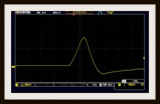
To expand on the hammer/accelerometer project I thought it might be useful to show what the sensitivity of the hammer's force transducer is when used in a typical impact test. I'm still in the calibration phase of these instruments so I'll just post a DSO screen shot of an average of 4 taps. The test specimen is a 1 sq-ft piece of 3/4" thick MDF sitting on some soft foam in my lap as I sipped some bourbon to see me through the task. I'll have the actual force measurement numbers soon.
As can be seen the impact produces a half sine wave with an amplitude of ~ 600 mV into the scope's 1 Megaohm input resistance. The sag on the right side of the waveform is leakage as can be expected from such a low resistance load. One of the interesting things about this type of testing is that the half sine signal contains infinitesimally small separations between the frequencies it's composed of.
As can be seen the impact produces a half sine wave with an amplitude of ~ 600 mV into the scope's 1 Megaohm input resistance. The sag on the right side of the waveform is leakage as can be expected from such a low resistance load. One of the interesting things about this type of testing is that the half sine signal contains infinitesimally small separations between the frequencies it's composed of.
Attachments
Using a 10X probe would definitely improve the leakage issue on the force sensor. Using a charge amplifier on the front-end would be ideal. A voltage amplifier would be a good second choice. The thing is that I'm trying to present is an easier and much more affordable way to arrive at some of what a true modal analysis can provide for making enclosures. Much of the testing and measuring can be done before the actual construction begins.
Here is a link to some info on only what the instrumented hammer can provide for materials selection. https://endevco.com/news/newsletters/2016_02/f_ate.htm
The point here is that a frequency spectrum can be generated by just tapping the part that you're interested in evaluating. The amplitude and spectrum from the tap is as shown in the link. You just have to choose the hammer's tip material that you think will give the best spectral content for your test. The impact typically lasts only mS. The information it generates is enormous.
If the box is already built its quality can be tested in the same way. It's the old knuckle rap test, but with real numbers as a result of the measurement. A microphone could be used in place of an accelerometer, but the results may be ambiguous. Microphones listen. Accelerometers feel.
I hope this all makes sense on some level.
You can get a charge amp pretty cheaply. Endevco 2775A Signal Conditioner | eBay No I need to explore getting the special hammer. The software looked really interesting. is there a free version floating on the web?
[FONT=Arial, Helvetica, sans-serif]Selecting the correct modal hammer
Question
I have to carry out a modal test in order to identify the dynamic properties of my test specimen. Is there any rule that could help me in selecting the right modal hammer with respect to e.g. specimen size and mass?
Answer
There is no fixed rule that would provide a clear indication which modal hammer is the most appropriate one to carry out the test. Although there is a set of aspects/factors that has to be considered before the choice of modal hammer is made.
Factor 1. Frequency bandwidth
Modal testing carried out with a modal hammer is based on providing the impact to the specimen, resulting in vibration over a broad frequency bandwidth. The width of frequency band of excited vibration depends on the impact duration. The shorter the pulse width, the higher the frequencies being excited. The impact duration can be changed by mounting special hammer tips of different stiffness. The different hammer tips allow various frequency bandwidths to be excited with the modal hammer, impacting the specimen with the same energy (the softer the hammer tip, the longer pulse, the narrower the excited frequency bandwidth).
[/FONT]
[FONT=Arial, Helvetica, sans-serif]
The final duration of the pulse, in certain cases, may also depend on the stiffness of the specimen that is being impacted. It is also important to remember that when a hard tip is used, the energy of the impact is being distributed over a wide frequency bandwidth, which means the power spectral density of the excitation may be low in certain cases, too low, to excite specimen vibration modes/resonances. In such cases we may try to hit the structure under test harder by taking a more robust swing or increasing the mass of the hammer by adding a head extender. Unfortunately this approach may also increase the risk of saturating the IEPE force transducer. Therefore, in certain cases, the change to the hammer model featuring a larger measurement range may be considered. Another solution is the application of a softer tip. This results in the energy of the impact being concentrated at lower frequencies (discussed in follow on section).
Factor 2. Amplitude of the pulse
The type of tip being used strongly influences the shape of the impact pulse - not only its duration but also its amplitude. Below graphic shows the force pulses of equal energy applied to the specimen having different hammer tips.
Usage of a hard hammer tip may imply usage of a modal hammer featuring a high measurement range force transducer. The lower measurement range force transducer may limit the usage of the hard hammer tips, which will not allow exciting vibration of high frequencies.
Factor 3. Mass of the hammer, Energy of the impact
The variety of shapes and masses, as well other properties of tested objects, like stiffness or damping require a variety of force pulses of different parameters for proper excitation. In general small compact objects tend to feature higher resonance frequencies and require lower energies of impact to be excited compared to large objects. Therefore in order to excite a small structure most likely at low energy, a short lasting force will be needed. Such a pulse can be provided with small and medium hammers like Endevco 2301 or hammers from Endevco 2302 family. Larger structures will require higher energy impact, most likely concentrated in a low frequency bandwidth. In such cases, larger hammers like Endevco 2303 2304 2305 with soft or medium stiffness tips, will be more appropriate to provide the force pulse excitation desired.
Factor 4. Tests repeatability
To be able to provide the mechanical excitation, of a desired parameter, we need to choose between different force measurement ranges, hammer tips and hammer masses. In practice during modal testing the hammer impacts performed by the operator may differ from one to the other, in terms of impact energy and frequency bandwidth of excited vibrations, as well as the angle of impact. Because of that a common practice is to average several results obtained in particular measurements. The objective is to obtain good quality, repeatable data results obtained in the particular measurements, being as similar as possible.
Modal hammers are available in number of different masses so the hammer operator can provide force pulses of different energies without the necessity of taking big swings during which it is difficult to control the force and angle at which the hammer tip impacts the structure.
[/FONT]
Question
I have to carry out a modal test in order to identify the dynamic properties of my test specimen. Is there any rule that could help me in selecting the right modal hammer with respect to e.g. specimen size and mass?
Answer
There is no fixed rule that would provide a clear indication which modal hammer is the most appropriate one to carry out the test. Although there is a set of aspects/factors that has to be considered before the choice of modal hammer is made.
Factor 1. Frequency bandwidth
Modal testing carried out with a modal hammer is based on providing the impact to the specimen, resulting in vibration over a broad frequency bandwidth. The width of frequency band of excited vibration depends on the impact duration. The shorter the pulse width, the higher the frequencies being excited. The impact duration can be changed by mounting special hammer tips of different stiffness. The different hammer tips allow various frequency bandwidths to be excited with the modal hammer, impacting the specimen with the same energy (the softer the hammer tip, the longer pulse, the narrower the excited frequency bandwidth).
[/FONT]
[FONT=Arial, Helvetica, sans-serif]
An externally hosted image should be here but it was not working when we last tested it.
[/FONT][FONT=Arial, Helvetica, sans-serif] 
The final duration of the pulse, in certain cases, may also depend on the stiffness of the specimen that is being impacted. It is also important to remember that when a hard tip is used, the energy of the impact is being distributed over a wide frequency bandwidth, which means the power spectral density of the excitation may be low in certain cases, too low, to excite specimen vibration modes/resonances. In such cases we may try to hit the structure under test harder by taking a more robust swing or increasing the mass of the hammer by adding a head extender. Unfortunately this approach may also increase the risk of saturating the IEPE force transducer. Therefore, in certain cases, the change to the hammer model featuring a larger measurement range may be considered. Another solution is the application of a softer tip. This results in the energy of the impact being concentrated at lower frequencies (discussed in follow on section).
Factor 2. Amplitude of the pulse
The type of tip being used strongly influences the shape of the impact pulse - not only its duration but also its amplitude. Below graphic shows the force pulses of equal energy applied to the specimen having different hammer tips.
An externally hosted image should be here but it was not working when we last tested it.
Usage of a hard hammer tip may imply usage of a modal hammer featuring a high measurement range force transducer. The lower measurement range force transducer may limit the usage of the hard hammer tips, which will not allow exciting vibration of high frequencies.
Factor 3. Mass of the hammer, Energy of the impact
The variety of shapes and masses, as well other properties of tested objects, like stiffness or damping require a variety of force pulses of different parameters for proper excitation. In general small compact objects tend to feature higher resonance frequencies and require lower energies of impact to be excited compared to large objects. Therefore in order to excite a small structure most likely at low energy, a short lasting force will be needed. Such a pulse can be provided with small and medium hammers like Endevco 2301 or hammers from Endevco 2302 family. Larger structures will require higher energy impact, most likely concentrated in a low frequency bandwidth. In such cases, larger hammers like Endevco 2303 2304 2305 with soft or medium stiffness tips, will be more appropriate to provide the force pulse excitation desired.
Factor 4. Tests repeatability
To be able to provide the mechanical excitation, of a desired parameter, we need to choose between different force measurement ranges, hammer tips and hammer masses. In practice during modal testing the hammer impacts performed by the operator may differ from one to the other, in terms of impact energy and frequency bandwidth of excited vibrations, as well as the angle of impact. Because of that a common practice is to average several results obtained in particular measurements. The objective is to obtain good quality, repeatable data results obtained in the particular measurements, being as similar as possible.
Modal hammers are available in number of different masses so the hammer operator can provide force pulses of different energies without the necessity of taking big swings during which it is difficult to control the force and angle at which the hammer tip impacts the structure.
[/FONT]
- Status
- This old topic is closed. If you want to reopen this topic, contact a moderator using the "Report Post" button.
- Home
- Design & Build
- Equipment & Tools
- Enclosure vibration measurements