A few weeks ago I saw this tubetester for the first time on ebay:
DIGITAL TUBE TESTER - LAMPEMETRE AUTONOME ULTRA COMPACT | eBay
I wondered if it would be any good; it seemed to good to be true. I searched if there were people who had any experience with it, but could find nothing. There was some information, but it was all in French; not my strongest language .
.
I decided to take the chance and order one, and put the experience here on diyaudio. Perhaps some tube lovers will benefit from it.
After I ordered it, I sent an email to the seller; "Rimlok" who had a very good reputation. I asked if he could sent me the manual in english in advance so I could start reading. I got an answer with the manual within 10 minutes, so that went well.
I ordered 20-1 and it arrived 24-1 so that was quick!
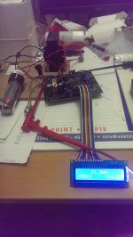
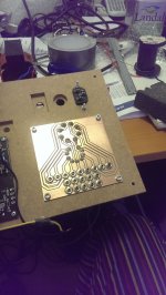
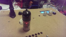
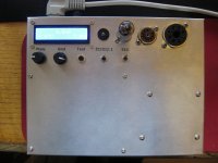
In about an hour I had it working and was testing my first tube; see picture.
The tester works really simple; it has two knobs for setting Va (anode/plate voltage) and -Vg (grid (bias) voltage).
If you push the test button it measures the Ia (anode/plate current). It measures pulsed so the tube is safe from overload.
You have to know what you're doing with these kind of testers, because you have to interpret the measurement yourself.
Manuals for vintage tubetesters are easily found on google; you can base setting on these, or use tube-curves to determine a measurement point.
For example: In an old AVO manual I saw that EL34 is mostly tested at Va 250v and -Vg -13.5v. According to the manual 75mA should be "new".
The meter measures in pseudo triode mode. There is an add-on in the manual to build a screen grid supply for true pentode measurements, but I decided to leave that be for now.
I quickly found out that al my old RFT EL34 are in different conditions, but not one broken. To my surprise, I had ordered 4 new electro harmonix el34 in october last year from "elektrodump.nl", 3 of the 4 tubes were defect. This was easy to see on the display, they were pulling grid current (gassy), so the negative Vg drops as the measurement starts. One of them even started flashing in the tube! As you can imagine I was a little bit disappointed... but after telling "elektrodump" my findings, they offered to replace the tubes free of charge! So the tubetester paid itself immediately back!
In the next posts, (if you are interested) the design/build experience, with some caveats here and there... (and a lot of pictures)
Paul
DIGITAL TUBE TESTER - LAMPEMETRE AUTONOME ULTRA COMPACT | eBay
I wondered if it would be any good; it seemed to good to be true. I searched if there were people who had any experience with it, but could find nothing. There was some information, but it was all in French; not my strongest language
.I decided to take the chance and order one, and put the experience here on diyaudio. Perhaps some tube lovers will benefit from it.
After I ordered it, I sent an email to the seller; "Rimlok" who had a very good reputation. I asked if he could sent me the manual in english in advance so I could start reading. I got an answer with the manual within 10 minutes, so that went well.
I ordered 20-1 and it arrived 24-1 so that was quick!
In about an hour I had it working and was testing my first tube; see picture.
The tester works really simple; it has two knobs for setting Va (anode/plate voltage) and -Vg (grid (bias) voltage).
If you push the test button it measures the Ia (anode/plate current). It measures pulsed so the tube is safe from overload.
You have to know what you're doing with these kind of testers, because you have to interpret the measurement yourself.
Manuals for vintage tubetesters are easily found on google; you can base setting on these, or use tube-curves to determine a measurement point.
For example: In an old AVO manual I saw that EL34 is mostly tested at Va 250v and -Vg -13.5v. According to the manual 75mA should be "new".
The meter measures in pseudo triode mode. There is an add-on in the manual to build a screen grid supply for true pentode measurements, but I decided to leave that be for now.
I quickly found out that al my old RFT EL34 are in different conditions, but not one broken. To my surprise, I had ordered 4 new electro harmonix el34 in october last year from "elektrodump.nl", 3 of the 4 tubes were defect. This was easy to see on the display, they were pulling grid current (gassy), so the negative Vg drops as the measurement starts. One of them even started flashing in the tube! As you can imagine I was a little bit disappointed... but after telling "elektrodump" my findings, they offered to replace the tubes free of charge! So the tubetester paid itself immediately back!
In the next posts, (if you are interested) the design/build experience, with some caveats here and there...
(and a lot of pictures)Paul
Attachments
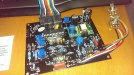
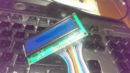
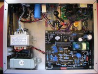
I believe I didn't mention it before, but if you order the tester, you get a completely build pcb, and a small pcb with the display. The flatcable between the two pcb's and the potmeters are also included. The complete module is powered through a single 6-9v ac connection, approximately 600mA. It generates the Va (plate voltage) and Vg (grid voltage) through an inverter!
I used an old tube transformers its 6.3v output; worked perfect.
As I was planning to be able to use 6.3v heater as well as 5v, I swapped the transformer for a 9v toroid later on. There is room included on the pcb for a lm317, but more on that later.
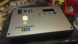
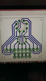
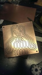
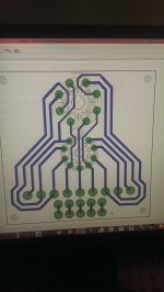
The thing I did after the first tests is design a connector print. As I planned to make a nice enclosure for it, this seemed like a logical step.
I wanted to use mini banana connectors; alas I was impatient and started designing before they were in my posession. Of course they were bigger then expected and I had to redesign.
Then I designed the front of the enclosure; i was afraid the loose pcb would be broken soon. Now I could assemble the parts.
I used an old tube transformers its 6.3v output; worked perfect.
As I was planning to be able to use 6.3v heater as well as 5v, I swapped the transformer for a 9v toroid later on. There is room included on the pcb for a lm317, but more on that later.
The thing I did after the first tests is design a connector print. As I planned to make a nice enclosure for it, this seemed like a logical step.
I wanted to use mini banana connectors; alas I was impatient and started designing before they were in my posession. Of course they were bigger then expected and I had to redesign.
Then I designed the front of the enclosure; i was afraid the loose pcb would be broken soon
. Now I could assemble the parts.Attachments
if you order the tester, you get a completely build pcb, and a small pcb with the display.
Nice. It's an emission tester, so it doesn't measure small signal characteristics like transconductance. Maybe this could be added later with some external circuitry.
Nice. It's an emission tester, so it doesn't measure small signal characteristics like transconductance. Maybe this could be added later with some external circuitry.
There is a rather extensive manual included, which shows you how to calculate Rp and GM (transconductance), from simple measurements.
If you for example change Vg 1v, the difference in Ia IS the GM.
But I agree that is not quickly done. The same seller also sells a curve tracer for cheap; that one measures GM and Rp, including the curves, but it needs a PC. I have ordered that one too. I will make a similar tread like this one for it.
The same seller also sells a curve tracer for cheap; that one measures GM and Rp, including the curves, but it needs a PC.
I have ordered that one too. I will make a similar tread like this one for it.
The curve tracer sounds really interesting also. Everybody has a pc.

I built one too for testing small battery powered radio tubes, novals, and octals. Worked great for me
Nice work
I see you used the little neon lamp which was included; how is it connected, and why is it useful? Not to see that the meter is powered on; the display gives that away
Nice work
I see you used the little neon lamp which was included; how is it connected, and why is it useful?
Not to see that the meter is powered on; the display gives that away
Neon lamps can be used like a 90V zener for overload, limiting, etc.
Maybe it shows the HV is active.
Its main purpose is to indicate a shorted tube, but it also blinks as the circuit tests the tube which is, umm, interesting. Looks like its wired across the test switch with a current limiting resistor, but i dont have the documentation to hand to double check that. The diagram in there will show you how to connect it up.
I am also interested in the curve tracer he offers, that's been on my eBay watch list for a while...
I am also interested in the curve tracer he offers, that's been on my eBay watch list for a while...
Hello ,
I build this tube tester with the curve tracer from this seller in the same box and you can switch between this two applications and also a regulated HV power supply .
Kind regards , Alexander .
I build this tube tester with the curve tracer from this seller in the same box and you can switch between this two applications and also a regulated HV power supply .
Kind regards , Alexander .
An externally hosted image should be here but it was not working when we last tested it.
An externally hosted image should be here but it was not working when we last tested it.
An externally hosted image should be here but it was not working when we last tested it.
How high can it go on the hv for the curve tracer? 700v possible?
Nope; according to manual 480v max.
Hello ,
I build this tube tester with the curve tracer from this seller in the same box and you can switch between this two applications and also a regulated HV power supply .
Kind regards , Alexander .
That looks really good. Also a good idea to build them together; so they can share the powersupply.
The curvetracer came in yesterday, and I spend the evening trying to get it to behave. Unfortunately it doesnt want to. It produces curves, but approx. 50% of the expected values... for example a new EL34 RFT measures 107mA at 250v/-13.5v on the tester. On the curvetracer curves it measures only 50mA...
It could be the 24v supply for the tracer as I have only had a 22.5v ac supply. I'm going to test with a "real" 24v one tonight.
I talked about the empty space on the board for the LM317. If you want to use this possibility, don't do it!
The circuit on the PCB is wrong(LM317 placement), there is no space for a rectifier.
If you want to use a LM317 for the heater, you are better of making a separate PCB. Had I noticed this upfront, I would have included it on the connecterboard.
The circuit on the PCB is wrong(LM317 placement), there is no space for a rectifier.
If you want to use a LM317 for the heater, you are better of making a separate PCB. Had I noticed this upfront, I would have included it on the connecterboard.
The curve tracer sounds really interesting also. Everybody has a pc.
Not me! I have used Macintosh since 1989
Not me! I have used Macintosh since 1989
Yes, so do I, but PCs are so cheap that you could get one just for this purpose.
Yes, I've had a look at Windows in several of it's guises - NT, XP, Vista etc - and that'd be another whole operating system to learn - yes, the hardware is cheap as chips, but the real cost is in the time it takes to learn how to use the system.
I'm not arguing that one system is necessarily better than another, but having to use a new operating system for a particular purpose is quite resource-intensive.
I did try to get a Windows machine operational to use some audio test software which I need, but Windows is so different from the systems I'm used to that I found it easier to build hardware to do the job.
- Home
- Design & Build
- Equipment & Tools
- Cheap (<100€) Digital Tube Tester from ebay; experience/build/mod thread