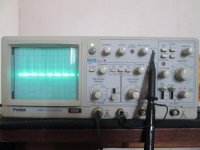
I bought a used Protek 20mhz oscilloscope it arrived in the mail with a broken plastic voltage setting thingo on the back next to the power plug,I made that safe but I cant calibrate the scope? On the front it has a metal tag to attach a probe to get 0.5v and it is supposed to appear on the screen as a square wave? Ive uploaded some photos of it, Ive adjusted the probe, VR1201 and VR33 but its still out of wack? Every now and then I can hear a single (crack) like a high voltage arc coming from the front display area? Any ideas on what I should do from here?
Attachments
At first make sure you use the correct vertical sensitivity (VOLTS/DIV)--it looks like the one you've chosen is far too high.
Samuel
Ive got it set to the right recommended value? Ive followed the instructions to the letter.
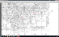
From reading another thread on DIY,Ive tracked the electrical arcing to the back of the scope to 2 neon lights next to the high voltage transformer NE1204 and NE1205.The solder side of the neons is under a metal plate. I can see underneath the plate with a torch that there isn't any carbon markings from the arcing there or on the top.I think that this is more than likely the problem. Im still trying to work out the schematic for this scope.The one I downloaded from Elektrotanya is about 6/7 different manuals and I'm still trying to work out whats what?
Last edited:
OK, Ive checked things out and it looks like its been arcing over a 1 watt 22 Mohm resistor (The resistor had been pushed down and was arcing between its pins,so I pulled it back up and straightened the legs) The resistor leads to an N-fet transistor, 2sk304e,TR1001 and to the neon lights. I measured the N-fet in circuit the best I could and it looks like its shorted, .004v from gate to source and .004v from gate to drain.So that's it until I get another 2SK340e N-fet. I know that FETs don't like static let alone arcing.LOL
Thanks for your concern fellas but don't worry I'm very, very careful.I learnt a lesson back in the early 1960s when I was about 12 y/o me and some mates climbed a 300,000v power pylon for something to do. I was just starting to climb up when my mate at the top got zapped! It looked surreal,it blew his clothes off and he fell with smoke coming off of him, then he hit the barbed wire skirt,he bounced off that and landed flat on his back which (they say)started his heart up again.I will never forget it,he was naked except for a plastic belt that was still bubbling around his waist.Anyway he lived through it.I met him at a pub years later but I didn't recognize him because he had plastic surgery to his face and hands but then he lifted his sleeves and trouser leg and I could see the scars.I would say he looks even better after the plastic surgery to his face,they did such a good job you couldn't tell.
The calibration value is unreadable in the fuzzy cellphone picture, but if it is 0.5V (PP?) as you claim and scope sensitivity is visibly set on both channels to 5 mV, squarewave will be 25 to 100 times taller than the screen .... by the way what's seen in the picture.Ive got it set to the right recommended value? Ive followed the instructions to the letter.
Only way for it to be recommended by the Factory would be involving a 100X probe , which would turn 500mV into proper 5mV ... not so sure you are doing that.
Thanks for your concern fellas but don't worry I'm very, very careful.I learnt a lesson back in the early 1960s when I was about 12 y/o me and some mates climbed a 300,000v power pylon for something to do. I was just starting to climb up when my mate at the top got zapped! It looked surreal,it blew his clothes off and he fell with smoke coming off of him, then he hit the barbed wire skirt,he bounced off that and landed flat on his back which (they say)started his heart up again.I will never forget it,he was naked except for a plastic belt that was still bubbling around his waist.Anyway he lived through it.I met him at a pub years later but I didn't recognize him because he had plastic surgery to his face and hands but then he lifted his sleeves and trouser leg and I could see the scars.I would say he looks even better after the plastic surgery to his face,they did such a good job you couldn't tell.
Ouch !!!!!

It hurts just reading it
Glad you were too late for the main show.
The calibration value is unreadable in the fuzzy cellphone picture, but if it is 0.5V (PP?) as you claim and scope sensitivity is visibly set on both channels to 5 mV, squarewave will be 25 to 100 times taller than the screen .... by the way what's seen in the picture.
Only way for it to be recommended by the Factory would be involving a 100X probe , which would turn 500mV into proper 5mV ... not so sure you are doing that.
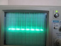
Time division is set on .5ms and Volts division is set to calibration 5mv Fully clockwise?
Last edited:
Time division is set on .5ms and Volts division is set to calibration 5mv Fully clockwise?
Well, 5 mV/div is definitely not right. The vernier (the little inset knob on the vertical) should be fully clockwise. The vertical control should be at probably 0.5 V/div. Then you can adjust the vertical sensitivity and position from there to fit the square wave to the screen.
the calibration pot is a variable resistor if you want the display to be a bit smaller. If you turn the callibration pot from the switched cal position the display will no longer be calibrated. the outside selector switch is rotated to select the correct volts per division. If you have a 10x probe(the probe divides the signal by 10 not amplifies it) and if there is a switch on the probe 10x 1x put the probe in the 10x position, turn the outside selector sw to 50 mv/division, or 20mv/division and adjust the trigger settings for a proper stable display. Adjust the trimmer cap on the probe, if any, for a proper square wave. Your scope may also have a horizontal cal pot as well. If the hor cal pot is not in the correct position the time base will be incorrect as well.
Remember you are not calibrating the volts/division you are setting the High Frequency response of the scope probe.
Remember you are not calibrating the volts/division you are setting the High Frequency response of the scope probe.
Last edited:
Well, 5 mV/div is definitely not right. The vernier (the little inset knob on the vertical) should be fully clockwise. The vertical control should be at probably 0.5 V/div. Then you can adjust the vertical sensitivity and position from there to fit the square wave to the screen.
What I have set it at are what the instructions say? The volts division is turned fully clockwise as is the other one on the same pot stem.This is just making me confused? How can the calibration be different to what the instructions say?
I have set the scope for calibration ,set the probe trimmer, lined up the square wave as best as I can ,Ive adjusted VR1200 horizontal and VR33 as well but it hasn't made any difference? That's why I think the N-fet is shorted because Ive tried everything else it seems?the calibration pot is a variable resistor if you want the display to be a bit smaller. If you turn the callibration pot from the switched cal position the display will no longer be calibrated. the outside selector switch is rotated to select the correct volts per division. If you have a 10x probe(the probe divides the signal by 10 not amplifies it) and if there is a switch on the probe 10x 1x put the probe in the 10x position, turn the outside selector sw to 50 mv/division, or 20mv/division and adjust the trigger settings for a proper stable display. Adjust the trimmer cap on the probe, if any, for a proper square wave. Your scope may also have a horizontal cal pot as well. If the hor cal pot is not in the correct position the time base will be incorrect as well.
Remember you are not calibrating the volts/division you are setting the High Frequency response of the scope probe.
Ive found an open rectifier type diode D1012 going to the high voltage coil as well, I'm surprised this scope is even working at all? I cant see any arcing across R1017 anymore in fact I cant see where its coming from now but I can hear it coming from the back right hand side.I left the scope over night and when I first turned it on again I heard arcing for about 2 seconds.I turned it off then on again and there is no further arcing?
Attachments
Have you ever used a scope before?
you cannot properly set the probe trimmer without seeing the top and bottom of the calibration signal.
Is your probe set to 1x or 10x?
lets say it is 10x and your cal signal is 500mv.
set the inside vernier cal pot to cal position.
set the outside voltage per division sw to 50mv/division
you should see a square wave of 1 division high (500mv divided by 10)
if you set the volts/division to 5mv/division then the display will be 10 divisions high and may be off the screen. This is what is shown on your first post.
turn the vertical position knob till the display is centered.
on your pictures you have selected DC coupling for channel 1. I have a feeling that the cal signal goes from 0volts to +500mv. Try setting the coupling to AC and the display may center for you and not go off the screen.
google how to use a scope basics
set triggering to internal and AC, adjust the triggering slope +/- for a stable display
Yes,I have used an oscilloscope before.I have set this scope to the recommended settings plus every other conceivable setting to try and get it to work? I understand how they work,1, 5 and 10 x attenuation etc... but this one I realize now has an electronic problem.The diode I measured with my DMM on diode setting didn't read anything, forward or backward voltage? I'm not really sure about the N-fet transistor because I measured it in circuit but chances are its had it also because of the high voltage arcs to the gate coming from R1017.
- Status
- This old topic is closed. If you want to reopen this topic, contact a moderator using the "Report Post" button.
- Home
- Design & Build
- Equipment & Tools
- Oscilloscope calibration?