Gents,
How about a thread here on the best methods of prototyping and breadboarding for tube circuits ? Im about to embark on a totally custom/expensive preamp project - so I intend on doing a prototype first...
Thanks !!
How about a thread here on the best methods of prototyping and breadboarding for tube circuits ? Im about to embark on a totally custom/expensive preamp project - so I intend on doing a prototype first...
Thanks !!
I've been wondering the same thing. I'm about to do my first build but I'm not actually sure how to put the circuit together as a prototype first... I'll figure it out real quick but I'd like to read what some folks with experience do as standard practice...
Personally I've never used these but they look like a good idea
http://www.tubesandmore.com/scripts...1=02_ACCESSORIES&SEARCH_TREE02=02_EPOXYBOARDS
http://www.tubesandmore.com/scripts...1=02_ACCESSORIES&SEARCH_TREE02=02_EPOXYBOARDS
I try and do all the theoretical stuff up front so that basic blocks are settled and all that needs doing is to alter values on passives and the like. I have yet to work out how to run Spice or similar, so for me its the calculator, sketchpad and coffee technique. Using this approach, my active components (generally the larger and more expensive bits) are all determined, so I can start building.
Since my builds are all p2p, I then set up the chassis with all the required bits mounted, and start slinging solder. I now have a working (hopefully) unit that can be optomised by adding, changing or deleting the various little bits that hang off the valve sockets, tag strips and the like.
This works for me for a couple of reasons - it takes away that urge to itteratively alter a design at the breadboard stage, that urge ending up as the end itself and the design never being actualised. I'm a procrastinator at the best of times so I don't need the excuse of "just one more design change..."
Secondly, (and associated) I quickly reach the deminishing returns point and so my device moves from the workbench to the lounge (or whereever) and the various significant others can tell me what a genius I am instead of whining about my lack of attention to their need for affirmation and affection. Never underestimate the motivational power of WAF
Gents,
How about a thread here on the best methods of prototyping and breadboarding for tube circuits ? Im about to embark on a totally custom/expensive preamp project - so I intend on doing a prototype first...
Thanks !!
I do as much homework as possible, then go directly to having PCB's made. If I doubt the outcome I have prototype PCBs without solder mask and silk screen, but almost always go with productions boards the first time I build.
My recommendation is to do a paper design and "show all your work". In other words, make copious notes of all your math calculations for the design. Put those notes into a nice neat, easy to read, format in an electronic document. Describe the theory of operation in those notes as you go.
Then, publish those notes with the design schematic here or on a website and invite the gang to do a review.
Two things will happen when you do this and they will both be surprises:
1) You will be surprised at the number of mistakes you will find before you publish it.
2) You will be even more surprised at the number of mistakes or improvements others will unearth after they review it.
Having a review is like having a whole gang of engineers doing the design. You get all kinds of ideas and in the end you get to decide if you want to use them or ignore them. After all, it is your gig.
Guys,
Thanks for all the tips. I'll be building this amp on a turret board; so I figure I will lay out the components on graph paper to build out a drill template. From there, I'll put it on some plywood to make it easy to get to different components that may need adjustment, to take measurements, etc. Once I have it where I want it, then I'll disconnect what I need to; and toss it in a chassis.
-Steve
Guys,
Thanks for all the tips. I'll be building this amp on a turret board; so I figure I will lay out the components on graph paper to build out a drill template. From there, I'll put it on some plywood to make it easy to get to different components that may need adjustment, to take measurements, etc. Once I have it where I want it, then I'll disconnect what I need to; and toss it in a chassis.
-Steve
Good plan. Another tip is if you have a computer and a printer, download one of those free cad packages (TurboCAD, maybe) and do a 1 to 1 layout on that. Then print it to actual scale on the printer.
I have used either spray on glue or even glue stick on the paper to fasten it to the surface you want to cut. Tape is a bad idea, but if you really want to know why, try it yourself. 😱
One trick is to draw a box of known height and width on the drawing page (i.e., the outline of the chassis works fine) and when you print the page, double check the known dimensions with the actual dimensions you measure of the sheet of paper. This confirms that the printer did not distort the layout, which you might not realize until after you are busy cutting metal.
I have been prototyping circuits for nearly 50 years. Of course my abilities have improved a bit.
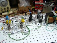
I have different prototyping methods for different applications. Sometimes you just have a vague idea and you just want to play with some parts. Soldering a circuit together seems like a waste of time if you know that you are going to be changing most of the parts before you are done, and many of them will get changed more than once. For those projects I use the "Tubelab". The first photo shows a prototype 6AV5 screen drive amp built in the Tubelab.
The Tubelab
The first generation Tubelab wasn't much more than some tube sockets screwed to a piece of plywood with a lot of clip leads to connect things up.
The second generation added a copper screen to the plywood to act as a ground plane. It also used individual "modules" which were PC boards with one or two tube sockets and a bunch of Fahnestock clips for the components. It was used to design the Tubelab SE amp. It was too big and took up most of my workbench, but did the job.
The third generation Tubelab used nylon pegboard for the base and the individual modules. There is still a copper screen under the base. "Euro barrier strips" are used for the interconnections and components. It is much smaller.
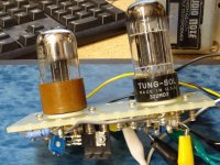
There are other times when the topology of the circuit, or at least the number of tubes and their types are known. The pre made turret boards in the link above allow for rapid prototyping, and can be used in the final amp if desired.
I have used them in situations where the circuitry is known, so the components are tacked on to the sockets and turrets. The second photo shows a prototype driver board being designed.
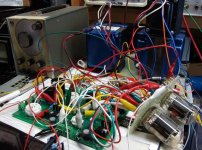
I have also used them where I had no clue what I was doing, but an amp was born anyway. The third photo shows two 6LR8's on the turret board, a Simple SE board, and about a million clip leads. I know that this isn't supposed to work, but it did!
I have different prototyping methods for different applications. Sometimes you just have a vague idea and you just want to play with some parts. Soldering a circuit together seems like a waste of time if you know that you are going to be changing most of the parts before you are done, and many of them will get changed more than once. For those projects I use the "Tubelab". The first photo shows a prototype 6AV5 screen drive amp built in the Tubelab.
The Tubelab
The first generation Tubelab wasn't much more than some tube sockets screwed to a piece of plywood with a lot of clip leads to connect things up.
The second generation added a copper screen to the plywood to act as a ground plane. It also used individual "modules" which were PC boards with one or two tube sockets and a bunch of Fahnestock clips for the components. It was used to design the Tubelab SE amp. It was too big and took up most of my workbench, but did the job.
The third generation Tubelab used nylon pegboard for the base and the individual modules. There is still a copper screen under the base. "Euro barrier strips" are used for the interconnections and components. It is much smaller.
Personally I've never used these but they look like a good idea
http://www.tubesandmore.com/scripts...1=02_ACCESSORIES&SEARCH_TREE02=02_EPOXYBOARDS
There are other times when the topology of the circuit, or at least the number of tubes and their types are known. The pre made turret boards in the link above allow for rapid prototyping, and can be used in the final amp if desired.
I have used them in situations where the circuitry is known, so the components are tacked on to the sockets and turrets. The second photo shows a prototype driver board being designed.
I have also used them where I had no clue what I was doing, but an amp was born anyway. The third photo shows two 6LR8's on the turret board, a Simple SE board, and about a million clip leads. I know that this isn't supposed to work, but it did!
Attachments
Last edited:
I have been prototyping circuits for nearly 50 years. Of course my abilities have improved a bit.
I have different prototyping methods for different applications. Sometimes you just have a vague idea and you just want to play with some parts. Soldering a circuit together seems like a waste of time if you know that you are going to be changing most of the parts before you are done, and many of them will get changed more than once. For those projects I use the "Tubelab". The first photo shows a prototype 6AV5 screen drive amp built in the Tubelab.
The Tubelab
The first generation Tubelab wasn't much more than some tube sockets screwed to a piece of plywood with a lot of clip leads to connect things up.
The second generation added a copper screen to the plywood to act as a ground plane. It also used individual "modules" which were PC boards with one or two tube sockets and a bunch of Fahnestock clips for the components. It was used to design the Tubelab SE amp. It was too big and took up most of my workbench, but did the job.
The third generation Tubelab used nylon pegboard for the base and the individual modules. There is still a copper screen under the base. "Euro barrier strips" are used for the interconnections and components. It is much smaller.
There are other times when the topology of the circuit, or at least the number of tubes and their types are known. The pre made turret boards in the link above allow for rapid prototyping, and can be used in the final amp if desired.
I have used them in situations where the circuitry is known, so the components are tacked on to the sockets and turrets. The second photo shows a prototype driver board being designed.
I have also used them where I had no clue what I was doing, but an amp was born anyway. The third photo shows two 6LR8's on the turret board, a Simple SE board, and about a million clip leads. I know that this isn't supposed to work, but it did!
Great idea and execution.
The third generation Tubelab used nylon pegboard for the base and the individual modules. There is still a copper screen under the base. "Euro barrier strips" are used for the interconnections and components. It is much smaller.
That thing is very cool. A simple, elegant solution.
Paul
Wild Burro Audio Labs - DIY Full Range Speakers
When it comes to connecting wires/components to the pins of the tubes I have several sockets soldered to the standard household electrical plastic connectors with the brass screws.
Easy to screw in wires/resistors etc to different pin configurations without any soldering.
I use these electrical connectors throughout the breadboard so its so simple to unscrew components and fit other values while you experiment.
Easy to screw in wires/resistors etc to different pin configurations without any soldering.
I use these electrical connectors throughout the breadboard so its so simple to unscrew components and fit other values while you experiment.
I use an old chassis from a TEK O-Scope, and solder components in place.
However, the second version of TUBELAB reminds me of the tube labs they had in the NAVY in 72. I never got to play with them because the navy switched from tube theory to transistor theory just before I got to 'A' School.
The third incarnation looks really nice, and I may need to build something similar to paly with. I would suggest switching from 1/4" bolts for locator pins to wooden dowels or nylon bolts as a safety precaution. It looks like some component leads could short against them in some instances.
second version of TUBELAB reminds me of the tube labs they had in the NAVY in 72.
The seeds were planted for that idea back in high school. We had a 3 year long vocational electronics program (1967 - 1970) that taught vacuum tubes. Most of our lab equipment was surplus from Homestead AFB, including the training manuals. There was some Navy and even Coast Guard stuff too. We had some breadboard labs that used a neat spring connector thingy that you just stuck the component leads into and the connection was made. Most of them were useless by the time we got them though.
I would suggest switching from 1/4" bolts for locator pins to wooden dowels or nylon bolts as a safety precaution. It looks like some component leads could short against them in some instances.
Probably a good idea since there is an ominous looking black mark on one of the bolts already. The whole 3rd generation thing came about in one afternoon when I decided that the old one was just too big. I cut the 2nd gen base in half with the table saw, and used what ever else I could find at Home Depot to build it. I had to hit every Radio Shack in the county to get enough of the "euro strips". Since then I found them by the box load at a surplus outlet. I am still looking for a quick wire connection that doesn't require a screwdriver.
I use .060 aluminum panels about one foot square with various octal and 9-pin sockets pre-installed. I build prototypes either by soldering or with clipleads. What really helps for prototyping are the bench supplies I've purchased and refurbished over the last few years. Nothing saves so much time as having a ready source of variable bias, variable B+ and common filament voltages.
I am still looking for a quick wire connection that doesn't require a screwdriver.
Fahnstock clips. Sringloaded, you insert a bare wire end into a slot and the spring loads up and holds it in place.
The third generation Tubelab used nylon pegboard for the base and the individual modules. There is still a copper screen under the base. "Euro barrier strips" are used for the interconnections and components. It is much smaller.
From what I can gather, the plastic pegboard is a "wet environment" material ONLY. When I try to get it in bone dry Colorado, people (including Home Depot personnel) give that "what planet are you from" look. The few online sources I have found are crazy $$$ considering how cheap Tubelab got this stuff for .... I have all the other compnents (including nylon locator bolts) - does anyone know a good (i.e cheap) source for the board?? thx much.
Anybody interested in entering a coastal to inland export arrangement?
Last edited:
Amazon.com: GeoMatrix PEGBOARD Pegmaster White Poly Pegboard: Home Improvement
$19 for a 2'x4' sheet
$19 for a 2'x4' sheet
Thx markr14850 -
However, the 'devil (as they say) is in the details'. I found it on Amazon before and was elated - but did you notice the shipping charge??? $211 for each sheet - no really - look. Reminds me of 'police-assisted suicide'. I don't think they REALLLLY want to sell any -- do you?? I need a nylon board not the golden one <grin>. It is the same everywhere I have found (low material cost; coocoo shipping cost). Not sure why. I got free shipping recently on some metal that was much bigger that this. Seems like a great market for someone out there.
However, the 'devil (as they say) is in the details'. I found it on Amazon before and was elated - but did you notice the shipping charge??? $211 for each sheet - no really - look. Reminds me of 'police-assisted suicide'. I don't think they REALLLLY want to sell any -- do you?? I need a nylon board not the golden one <grin>. It is the same everywhere I have found (low material cost; coocoo shipping cost). Not sure why. I got free shipping recently on some metal that was much bigger that this. Seems like a great market for someone out there.
Last edited:
Back in the 80's, I made a prototyping board out of nice oak. I put a bunch of 8pin relay sockets and some surface mount 4 and 5 pin sockets and a custom surface daughter board with 2 9pin sockets.
Each of the sockets has a row of screw terminals on two sides.
The sockets are down the middle and on the outside are rows of screw terminals that have insulation walls between the terminals, just like the sockets.
I put passive components (resistors, capacitors) and jumpers between the tube sockets and the rows of terminals.
I routed out channels under the board so I could route wires for filaments and main supply rails. Then only the signal lines are above the board.
I will try to post a photo. There used to be one on the VALVE site, from VSAC 1, but it is long gone.
I have implemented all kinds of tube circuits on this, with ease.
I use .060 aluminum panels about one foot square with various octal and 9-pin sockets pre-installed. I build prototypes either by soldering or with clipleads. What really helps for prototyping are the bench supplies I've purchased and refurbished over the last few years. Nothing saves so much time as having a ready source of variable bias, variable B+ and common filament voltages.
Hmm, sounds like the old metal tube circuit prototyping boards they used to use for schools. I actually have one of these. I should sell it since it hasn't been touched in decades. If anyone is interested let me know and I will dig it out and take some pics.
- Status
- Not open for further replies.
- Home
- Design & Build
- Equipment & Tools
- Breadboarding/Prototyping - How to and Tips/Tricks