Howdy everyone,
I'm wanting to do a valve I to V converter, and would like to work with chips with current out swinging around the vref (aka vcom2) point and not ground.
I.e the ad1853 and pcm1738
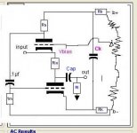
Attached is a circuit that I have used with chips whos current out swings around ground like the pcm63. This I to V converter is known as a Lohoff I to V, the idea comes from the TubeCAD program
I'm no tube guru, but for a dac with current out at vref and not ground, will I be able to eliminate the 2.7v vref voltage offset on the current outs by adjusting the bias on the grid aka "vbias"
OR do I have to float the whole valve circuit at the vref potential and transformer couple its output?, (probably after a buffer of some sort? )
I am sure I have seen this technique mentioned here before, but for the life of me canot find the post/thread
Regards,
Mark
I'm wanting to do a valve I to V converter, and would like to work with chips with current out swinging around the vref (aka vcom2) point and not ground.
I.e the ad1853 and pcm1738
Attached is a circuit that I have used with chips whos current out swings around ground like the pcm63. This I to V converter is known as a Lohoff I to V, the idea comes from the TubeCAD program
I'm no tube guru, but for a dac with current out at vref and not ground, will I be able to eliminate the 2.7v vref voltage offset on the current outs by adjusting the bias on the grid aka "vbias"
OR do I have to float the whole valve circuit at the vref potential and transformer couple its output?, (probably after a buffer of some sort? )
I am sure I have seen this technique mentioned here before, but for the life of me canot find the post/thread
Regards,
Mark
Attachments
Mark,
Are you running balanced?
You could take a sample from each cathode of your grounded grid stage using say a 1Mohm resistor and sum into a servo. The +ve input of the servo goes to VCOM. The output of the servo goes back to the grids. It would be be a good idea to fix bias the grids somewhere near their operating point (cathodes at VCOM). The servo will then pull the grids up or down around the fixed bias to trim the cathodes to the VCOM reference. That way you can be sure at start up that your cathodes will be somewhere within the range of VCOM.
All the best.
Mark,
>I'm no tube guru, but for a dac with current out at vref and not ground, will I be able to eliminate the 2.7v vref voltage offset on the current outs by adjusting the bias on the grid aka "vbias"<
By adjusting "Vbias" you will be able to set the input terminal to the circa 2.5V (my measurement on a PCM1738) that is coming out of the DAC.
It should work OK, and *maybe* even sound great, but it won't be very DC stable - single ended/non-differential tube DC amps drift all over the place - and to do it properly it would need some form of an opamp based servo to hold it all in check.
Allen
AW said:Mark,
>I'm no tube guru, but for a dac with current out at vref and not ground, will I be able to eliminate the 2.7v vref voltage offset on the current outs by adjusting the bias on the grid aka "vbias"<
By adjusting "Vbias" you will be able to set the input terminal to the circa 2.5V (my measurement on a PCM1738) that is coming out of the DAC.
It should work OK, and *maybe* even sound great, but it won't be very DC stable - single ended/non-differential tube DC amps drift all over the place - and to do it properly it would need some form of an opamp based servo to hold it all in check.
Allen
Allen,
The bias stability of a common grid configuration on the DAC outputs was was covered comprehensively in post #3. A solution was also offered which addressed voltage compliance levels at the DAC output during startup, drift and tube replacement situations.
You may have missed it.
Regards, Craig.
Hi AW,
I thought that Mark was explaining his level of understanding and asking for an opinion of whether he was on the right track. I also believe Mark was looking for a complete solution. He mentioned a couple of options and I presented one which I believed would be a worthy performer.
I don't believe he was looking for a simple solution that "won't be very DC stable" and "drift all over the place". You did however mention op-amp based servo to "hold it all in check." which was already mentioned in post #3.
I thought you didn't read my post because you covered all the ground I had previously but presented a more pessimistic view of obtaining a solution. I believe for the sake of clarity it would be more helpful to refer and/or expand on what was already said than possibly confuse some readers by re-introducing what had been already introduced as something new and a less tidy solution to boot.
I see we do both believe that a servo is a solution for keeping the operating point of the cathodes at the VREF or VCOM level so it is in the voltage compliance range of the mentioned DAC chips.
To get back to Mark's solution - Mark I would recommend if possible to avoid any op-amp in the signal path. As brilliant as the OPA627 is it is not a contender when it comes to a properly implemented discrete transistor or vacuum tube circuit.
If you want any details for the servo or tube I/V feel free to ask. I am sure that many here can also answer that question for you or offer other solutions.
Hello
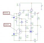
I work on a similar project, but for ad1865, then I have a reference at 0v, but the problem is the same.
My first simulation :
1ma give 15volts at the cathode follower output.
I made a regulation for the grid ref, tl431, zener and Diode for stability. This fixes the grid/cathode voltage.
The 2.5 volts ref of the tl431 is used for the css ref too (transistor base).
Only simulation for the moment.
Philippe
Attachments
Hello Craig and AW,
I am indeed looking for a complete solution, and would dearly like to try an all valve I/V (or one with transistor servo), and I too believe an opamp is not the ultimate answer. I have tried discrete transistor I/V's and would like to round out my experience with an all valve version if possible
Dac's having current out points referenced around non ground potential does make it a little trickier. Do you have any suggestions for a method of keeping the cathodes at vref? or any other solutions. I have not based my selection of the Lohoff circuit on any solid facts or arguments beyond the Tube Cad software's suggestions.
Regards,
Mark
Hi Mark,
The circuit you have there should work. You have the Vbias trim to set the upper tube cathode voltage to the reference voltage the DAC normal uses. You just need to make sure that during power startup or shutdown that the DAC output compliance range if exceeded does not have excessive current flow into or out of it.
There may or may not be clamp diodes on the output of the DAC chips to protect them from a ceratin amount of excessive output complaince range excursion. I am not sure from memory if that is covered in the datasheets for both the DAC chips you mention.
If you use the circuit you have already you can try different configurations to see what you prefer. You could put a servo on the Vbias point if needed but it may not be neccesary.
The circuit I had in mind would have just used the upper tube portion as the I/V with a current sink on the cathode side. The output signal would have been from the Anode load resistor through a DC blocking cap to a voltage follower buffer.
The Lohoff circuit you have does the pretty much the same thing but looks like it presents a lower impedance to the DAC o/p.
cheers, craig
philbyx,
Your circuit has the 6DJ8 I/V grid reference dependent on the negative rail. Simulate it with a different lower rail voltage and you will see what I mean.
You need to reference the bias voltage generator such as the diode to ground and resistor to the lower supply rail. That way your voltage reference will be referenced to ground or common.
A 6dj8 needs about -1.9 volts on its grid at 6 ma for the cathode to be at 0 volts. A LED is pretty close to that voltage.
CraigBuckingham said:philbyx,
Your circuit has the 6DJ8 I/V grid reference dependent on the negative rail. Simulate it with a different lower rail voltage and you will see what I mean.
The TL431 is a shunt regulator, which keeps the voltage between the negative rail and the ground constant.
The zener+diode maintain the grid at a constant voltage referenced to the negative rail.
Then the grid voltage is referenced to the ground and constant I think.
Philippe
Hi Philippe,
Yes it will work the way you have it but not ideal.
The circuit has two voltage generators in series with gnd. TL431 shunt more -ve to gnd then zener + diode referenced to TL431 to grid. -ve rail rejection is worsened as R25 sees noise voltage (rms sum) from D7, D12 & TL431.
Still low impedance to ground yes but more convoluted grid reference.
More noise on grid might not matter so much in this case as it is fed with a DAC current source/sink o/p.
Best to reference with low noise voltage generator -ve from ground and fed by current sink.
Regards CB.
- Status
- This old topic is closed. If you want to reopen this topic, contact a moderator using the "Report Post" button.
- Home
- Source & Line
- Digital Source
- valve i/v with 2.7volt vref