Hi there, looking to upgrade IV/amplification of this dac. dont like the sound( sintetics clear hights, dark midrange without texture,looking for more organic, open ,analogic sound)
as there is 4 chanel dac (actualy 5+1) and i use only two( thinking to simply paralel them (2+2) by paraleling data input and cuting wires from df1704) shoud
any ideas apreciated, thanks 🙂
as there is 4 chanel dac (actualy 5+1) and i use only two( thinking to simply paralel them (2+2) by paraleling data input and cuting wires from df1704) shoud
any ideas apreciated, thanks 🙂
Attachments
Looks like a lot of work to make that better. Fix/improve one area and the remaining areas that need work may be more audibly exposed.
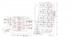
Looks like clock distribution design is far from ideal. Maybe running from a PLL instead of a crystal too, can't tell since it looks that signal comes in from some other board.
Easy things to play around with might include replacing the I/V opamps with OPA1612. Replace any caps in the audio path with at least 50v or 100v NPO, good film might be better (wound foil and polypropylene film are quite good but not cheap, good metalized film down a level but depends on exact cap design). Decoupling caps for opamps might be easy to swap, again good, low inductance, low ESR film can help a lot for decoupling analog circuitry (not ideal for digital though), but it depends. Have to try one thing at a time and see if you like it better, different, worse, or no change.
Clocking quality tends to affect sound quality significantly too. Change I/V so you like it better, and, again, you may just expose the next lower level problems more clearly.
Last edited:
Hi there, looking to upgrade IV/amplification of this dac. dont like the sound( sintetics clear hights, dark midrange without texture,looking for more organic, open ,analogic sound)
as there is 4 chanel dac (actualy 5+1) and i use only two( thinking to simply paralel them (2+2) by paraleling data input and cuting wires from df1704) shoud
any ideas apreciated, thanks 🙂
Is that a Denon AVR-5700?
If you don't like the DAC sound do you like the sound of the power amplifiers with an external source? [Some people like those power output devices and the power amp design.]
If you do like the sound of the power amplifiers with an external source and only use two of the DAC channels have you considered an external DAC? Have you heard one that you like that could be used with the AVR?
If you don't particularly like the sound of the power amplifier with an external source and you also don't like the sound of the DAC then you might consider that some people do like those AVR models and perhaps you would be better off selling it to someone who wants that DAC & Amplifier. (And getting a different one with a sound that you like.)
I say that since the PCM1704 chips are pretty expensive online and some people do like them. (They are in two pieces of my favorite gear.) The power amps have nice output power transistors too.
I don't think paralleling two PCM1704 will change the basic character of the sound. (If you don't like the character of the sound.)
its a Denon AVC-A1D
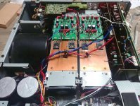
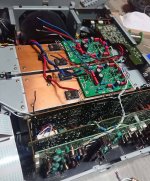
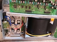
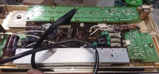
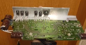
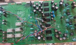
Well I like sound now much better, i did small upgrade to unit which seems change sound a bit
1) one of power suply modified and hided in front panel with custom heatsink. powersuply caps shunted wth variuos MKP (20-30psc) Need to fight with milimeters here.
2) dedicated ultrafast diodes and custom heatsink
3) omron DPDT relays for 5.6ohm load when speakers protection unload amp
4) video input/ output pcb boards removed and together with 1) enabled to fit second heatinks(total 4 fans and 4 heatinks) fitin is so tight it needed to machine aluminium – fight for milimeters not centimeters
5) 5 channel darlington type power amp section remooved(left only termo sensors) and dartzeel model 108 clone fitted. I needed DPDT realys to protect it (it would blow up and no feedback-goes to osicaltion) when amp security checks and enables outputs
6) removed/bypassed every single amplification from preamps,inputs left only toshiba analog volume regulators, around 26 operational amplifers left out
7) remooved ALL coupling caps in the signal path. there were 9 signal pssing caps per channel (45psc total) no DC ofset of any kind after removal in any secton, not sure why they used so many Elna Silmic caps in signal path..
8) bypassed cuted all signals from pcb to main boards and back, changed with silver and cooper wiring. , most not needed relays signal paht bypassed.
Even with those small changes I would say amp+ dac combo sounds completely diferent, if I would not know I would say its diferent amplifier!
I also thinkink for the last work – to paralel not used channels dac chips and replace OPA IV and OPA gain stage DAC IV with jfet analog stage.
Attachments
-
 147506814_1834621653352951_6305930783135092823_n.jpg661.9 KB · Views: 180
 -
 147660178_440896163726320_3217368295885111821_n.jpg661.5 KB · Views: 174
 -
 147687609_1379515692397000_6839147114902537222_n.jpg530.9 KB · Views: 160
 -
 143029614_489911918665498_5765448888906200242_n.jpg418.2 KB · Views: 151
 -
 144691247_329696401660665_5263846874766596393_n.jpg183.9 KB · Views: 100
 -
 145065109_237089984576530_7333809748248200471_n.jpg313.3 KB · Views: 110
 -
 146733552_420915862493889_1086709604541496156_n.jpg726.4 KB · Views: 114
Last edited:
ok, it seems you are serious about these mods.... here's a tip: check this link:
https://www.diyaudio.com/forums/digital-line-level/227677-using-ad844-105.html#post4408659
The title is misleading.... the actual IC for I/V conversion that should be used is AD811. This was the only current to voltage solution that worked well when I was playing with 1704's...
Read the attached pdf's !!!
Have fun
Looks like an interesting project! I like the approach suggested by Extreme_Boky.
The output current of the PCM1704 is quite low and it seems to benefit from CFB based I/V. I used the LME49713 for I/V with a PCM1702 in a Classe CDP.3 and it improved in a significant way.
When using a CFB, you may need to experiment with different feedback resistor values from 1.2K to 3K depending on the board layout and power supply decoupling. For this application carbon film resistors may have an edge due to the inductive nature of some metal film types. Capacitors should be removed from the I/V op amp feedback loop for stability when using a CFB.
no problem with current- on pcb there is 5x1704. paraleling them will be equal result as pcm63, just not sure what to do- paralel them or make balanced revert phase and feed them from al24 processor(there is outputs for the second pair and its used in other denons)
I think i will go discrete way with d1 mosfet ,its revision or j-fet CEN.
I think i will go discrete way with d1 mosfet ,its revision or j-fet CEN.
- Home
- Source & Line
- Digital Source
- Any ideas to improve IV/output of 1704 DAC and paraleling DAC's