I'm unsure which Forum this should go in, Source or DAC but seeing as the question is about the DATA from the Source, here we are.
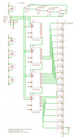
I am doing some very basic experiments with a 24 bit Ladder DAC, lots of resistors and a few shift registers. Very similar to the Sonic Solutions DAC, see the attached circuit. Mines not quite the same but very similar. My diagram is just a pencil sketch so far !
Early tests show it works but with a lot of noise, I have a long way to go yet ! Still, having a bit of fun !!
If I feed the DAC with 16 bit Data from a true i2S source (Philips CD Player pre the Filter or a SD Card Player I bought) the DAC seems to work and the MSB is where I would expect the MSB to be etc etc.
However, if I feed the DAC with 'converted EIAJ i2s' (see the circuit attached borrowed from Lampizator) the DAC sees the 16 bits but places them from the LSB 'upwards', if you see what I mean. So the MSB of the Data appears 8 bits 'down' from the DAC's MSB.
If I feed the 'converted i2S' into a TDA1541 (Pin 27 to +5V) it decodes it fine, but then it would, it's a 16 bit DAC chip.
I am obviously missing something in the differences between EIAJ and i2S.
Any help gratefully received.
P.
Attachments
'converted EIAJ i2s' - What in tarnations does this mangled abomination mean ?
Using the circuit from the Lampizator site, one is able to feed the EIAJ from, for example, a SONY CDP-227ES DSP IC, CXD1125 to a TDA1541A set for Two's Complement Input.
If the two are connected directly the TDA1541A will produce no O/P so some 'conversion' has to take place.
Forgive my terminology, we are not all experts on this DIY Forum.
We can't all be as brainy as you.

P.
NONE OF THIS STUFF REQUIRES BRAINS. It has been standardized for over three decades. Lego Mindstorms are more complicated. The electronics on my bicycle is more complicated. It simply requires following the basics. All you need to know is where you are and where you want to be.
There are three main serial formats.
I2S fixes the MSB position to one clock cycle after a transistion of wordclock.
MSB/Left justified data fixes the MSB to a position immediately after a transistion
of wordclock.
LSB/Right justified data fixes the LSB to the last position before a transistion of
wordclock.
With I2S and MSB/Left justified data the MSB is fixed and the LSB moves with
wordlength.
With the LSB/Right justified data the LSB is fixed and the MSB moves with
wordlength.
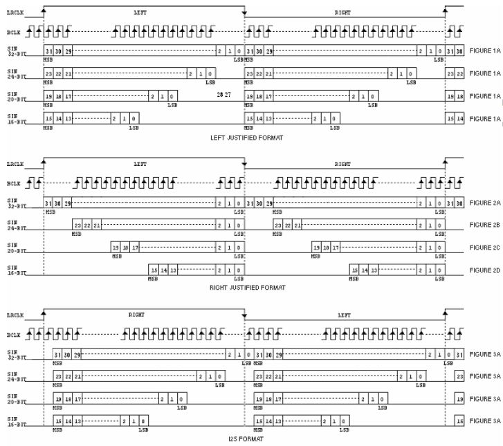
The I2S shown here crosses channels. LRCLK is usually drawn with Left channel first.
There are three main serial formats.
I2S fixes the MSB position to one clock cycle after a transistion of wordclock.
MSB/Left justified data fixes the MSB to a position immediately after a transistion
of wordclock.
LSB/Right justified data fixes the LSB to the last position before a transistion of
wordclock.
With I2S and MSB/Left justified data the MSB is fixed and the LSB moves with
wordlength.
With the LSB/Right justified data the LSB is fixed and the MSB moves with
wordlength.
The I2S shown here crosses channels. LRCLK is usually drawn with Left channel first.
Last edited:
Forgive my terminology, we are not all experts on this DIY Forum.
We can't all be as brainy as you.
P.
Given the sheer volume of information available and that, unlike days gone by, there are virtually no barriers to access to that information other than a willingness to use it, don't expect much sympathy from me.
The I2S shown here crosses channels. LRCLK is usually drawn with Left channel first.
Should read - The I2S shown here crosses samples. LRCLK is usually drawn with Left sample first.
Given the sheer volume of information available and that, unlike days gone by, there are virtually no barriers to access to that information other than a willingness to use it, don't expect much sympathy from me.
Many thanks for your replies and for the Table. Most useful.
I require no sympathy from you.
I just sought your 'forgiveness' as it seemed to irk you that I had asked a question to which it appeared you assumed was common knowledge amongst all who look at the Forum.
I can assure you I did as much research as I could into what format was being outputted from the CXD1125.
I can find no datasheet on my searches on the Net......
https://www.datasheetarchive.com/sony cxd1125-datasheet.html
CXD1125 Datasheet, PDF - Alldatasheet
cxd11 datasheet pdf, cxd11 data sheet, cxd11, cxd11.pdf, cxd11 pdf, cxd11 stock, cxd11 circuit, cxd11 datenblatt, block diagram, schematic, Datasheet4U.com
My use of the acronym EIAJ is a term I have seen used before to describe the DATA format outputted by many Japanese CD Players so I (perhaps incorrectly) used that term in post.
Searching Google for EIAJ doesn't throw up much information....
EIAJ - Google Search
And searching EIAJ in Wikipedia doesn'r help much either.......
Electronic Industries Association of Japan - Wikipedia
So, my question was posted here.
The Table you posted is from where may I ask? I have never come across this during my internet searches.
Anyway, it appears you may have provided me with the answer I was looking for, it's a shame it took four posts instead of you being able to post the table in your first reply. But going by our previous encounters of one another on here and, looking into your Post history it seems you enjoy answering other peoples inquiries with similar disdain and drawing out the post longer than is necessary.
So, many thanks again for the Table, I shall, hopefully, trouble you no further.
P.
...... But going by our previous encounters of one another on here and, looking into your Post history it seems you enjoy answering other peoples inquiries with similar disdain and drawing out the post longer than is necessary.
Then, I guess you see only what you want to see.
I am doing some very basic experiments with a 24 bit Ladder DAC, lots of resistors and a few shift registers.
...
Early tests show it works but with a lot of noise, I have a long way to go yet ! Still, having a bit of fun !!
P.
Wonderful project.
Did you build it?
Does it work?
Does it sound well?
regards
the resistance of switches is your limit for the real accuracy, if you use 7k5 and 15k resistors (2x15k parallel for 7k5), then you will need the resistor accuracy up to 0.00125% for 16 bits and its guaranteed monotonicity of output ...
16 bits is 15000R +- 0.19R ... 15 bits is +- 0.37R ... 13 bits is +- 1.5R ... and 12 bits is +-3R ...
on state resistance in these AHC595 switches is about 15R? +-1R? or even worse?
forget 24 bits (neither discrete R2R achieves this accuracy)
another huge problem will be glitch
16 bits is 15000R +- 0.19R ... 15 bits is +- 0.37R ... 13 bits is +- 1.5R ... and 12 bits is +-3R ...
on state resistance in these AHC595 switches is about 15R? +-1R? or even worse?
forget 24 bits (neither discrete R2R achieves this accuracy)
another huge problem will be glitch
0.1% accuracy is enough only for 10-bit DAC, you have to measure them more accurately (consider a low PPM, like 25ppm) ... 100k resistors sort in tolerance +-1.25ohm (0.00125%) ... you will need an accurate multimeter (6.5 digit)
try a simple RC deglitcher, although it is not enough ... track and hold opamp seems be fine, but it needs additional control logic and an analog switch...
try a simple RC deglitcher, although it is not enough ... track and hold opamp seems be fine, but it needs additional control logic and an analog switch...
- Status
- This old topic is closed. If you want to reopen this topic, contact a moderator using the "Report Post" button.
- Home
- Source & Line
- Digital Source
- Difference between true i2S and converted EIAJ