Hi mooly, where did you measure?I've just measured my old CD150 and it seems the resistors are chosen to add an almost +1v (measured +850mv) offset to the opamp chain. That offset carries through to the final electrolytic coupling cap.
Yesterday, I measured input @ pin 2 of the NE5532 opamps,
using a test CD with a digital zero track and a 1kHz full scale track. No voltage on my cheap multimeter
because of the AC swing I guess, but also no voltage using the voltmeter in AC mode as well...
But I measure about 3.6mA current, with digital zero as well as full scale signal.
If I am right here, is the injection just for lowering the current (why does not
not the I/V resistor do the job) or did I measure a 0.4mA loss because the part of current is forced to negative? (Can a current be negative btw?
 )
)Sorry for asking basics I missed at school...
All the best, Salar
Its a long time ago... I see that I said the offset carried through to the final opamp output. Its a DC voltage, not AC.
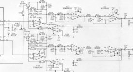
You would never be able to see any signal voltage on pin 2 of the first opamp because it is configured in a 'virtual earth' configuration. Whatever current is being sourced (or sunk) from the DAC, the opamp output matches it in the opposite direction via the feedback resistor to make sure that pin 2 and pin 3 are always the same voltage.
I've just noticed the - and + markings on the inputs of the second opamp are reversed although the pin numbers are correct.
You can have a 'negative' current which flows out of rather than into a node when talking in simple terms... look at the physics of it all though and it will tie you in knots.
So charge a capacitor and the current flows one way. Discharge the cap into a resistor and it flows the other way. Its not really negative, its just negative or opposite to the way it was originally.
Hi Mooly,
thanks a lot für the explanation.
Now if I was to use two TDA1541 in parallel, what values of the injection would
have to be changed. I assume, the Feedback resistor has to be halved in value as well?
Philips Service Manuals of the early CD-Players habve some errors, mainly because
they are based on the first generation circuits which were not properly adopted/updated to latzer models.
Found that some namings were wrong or some real world connections missing .i.e. the CD304MKII has a connector that carries a "kill" signal - but the description whre the Signal goes is missing or descriptions of checkpoints are missing...
All the best,
Salar
Two identical current sources in parallel would theoretically double the output from the first I/V opamp and so that would need the feedback altering to suit.
Wouldn't like to guess on the injected current because it would depend on exactly what the DAC has at its output under no signal conditions. If the DAC output were zero volts (when open circuit) then the injection values would actually stay the same because it would be the opamp output that changes voltage so as to deliver the same current via the feedback resistor as the injection resistor is supplying. The voltage at pin 3 (non inverting) is fixed at zero and so the opamp output alters to keep pin 2 the same.
So its a bit of an unknown not knowing exactly what the DAC will do.
Hi Mooly,
thanks for the answer! I am wondering:
The digital filter SAA7220A of the CD304MKII was betterd to a "B" Version
in later players using the TDA1541.
Type Differences Philips SAA7220P/A, /B & /C
Quote:
"The other difference between the two types is that the offset in the accumulator is greatly reduced (+0.05% in the 'B' compared to +5% in the 'A'). The SAA7220P/A required a +5% offset to give optimum performance when used with the TDA1541 dual DAC. However, with the 'B' version this offset is no longer necessary for optimum Performance"
Could it be that the 5% offset in early versions of the filter (as well as in the 14bit types) is the cause for the injection?
All the best,
Salar
That's a classic DC servo to maintain zero volts on the output... which is then (correctly imo) AC coupled anyway.
I wonder if the FET switching for de-emphasis introduces a shift in offset if there were no servo to correct it. I imagine it would be very very small though.
I wonder if the FET switching for de-emphasis introduces a shift in offset if there were no servo to correct it. I imagine it would be very very small though.
- Status
- This old topic is closed. If you want to reopen this topic, contact a moderator using the "Report Post" button.
- Home
- Source & Line
- Digital Source
- TDA1541-why is a Voltage fed into the Current Output?