I have some playstation-1's, some modded some stock. During the mods I managed to zapped the audio section of one board..... Maybe it can still work as a transport, I thought, all I have to do is pipe out the signal and use it to drive an external dac. It turned out the AKM chip's input signal uses Eiaj format, while I need I2s format to drive a TDA1541 dac.
Maybe there is a select pin in some chip upstream that can set Eiaj / I2s? Well, the research turned up nothing, I don't have a schematic and couldn't find datasheet for some of the chips.
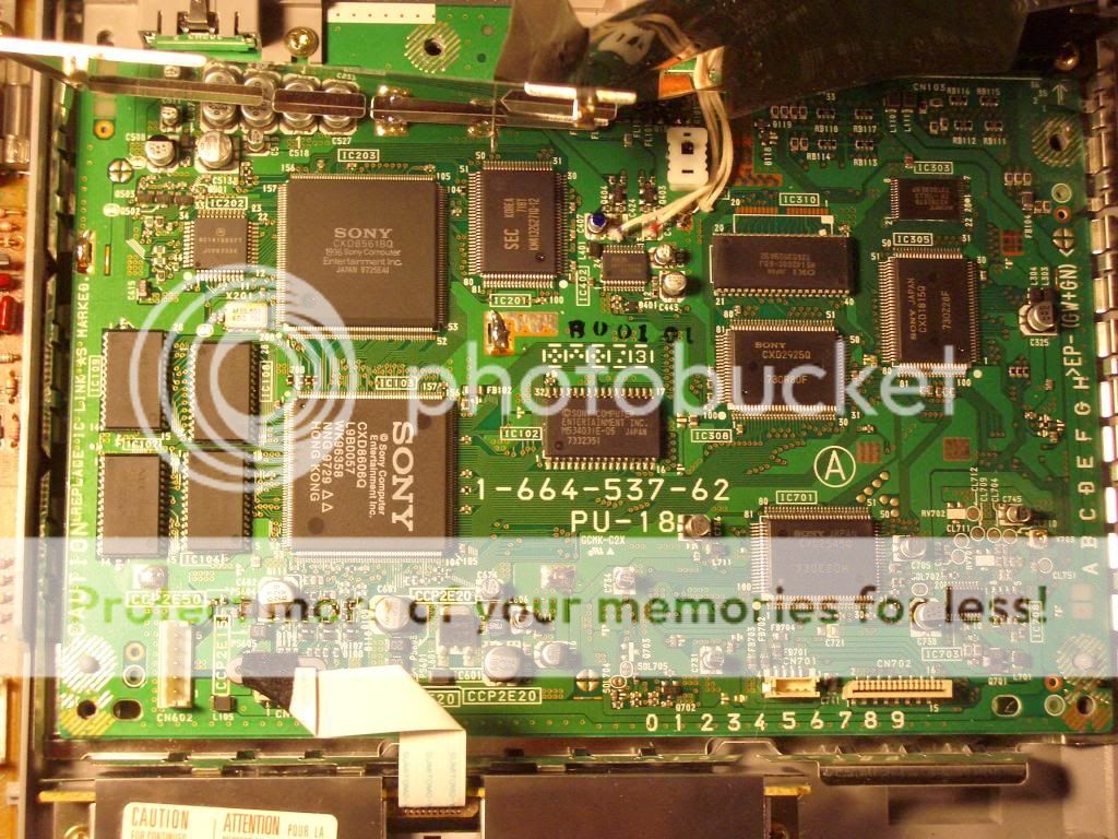
And then there is this CXD2510Q chip in the upper left corner of the board. I downloaded the datasheet, and was looking at the pin out's. According to the datasheet, Pin#60 is "Dout", Pin#59 is the pin to enable it.
...
...
Dout?
hmmm, like the Dout pin in a CXD2500?
...
...
... somehow I remember somebody somewhere mentioned the Dout in the cxd2500 is SPDIF, maybe this 2510Q has spdif output as well?.....🙄
....
....
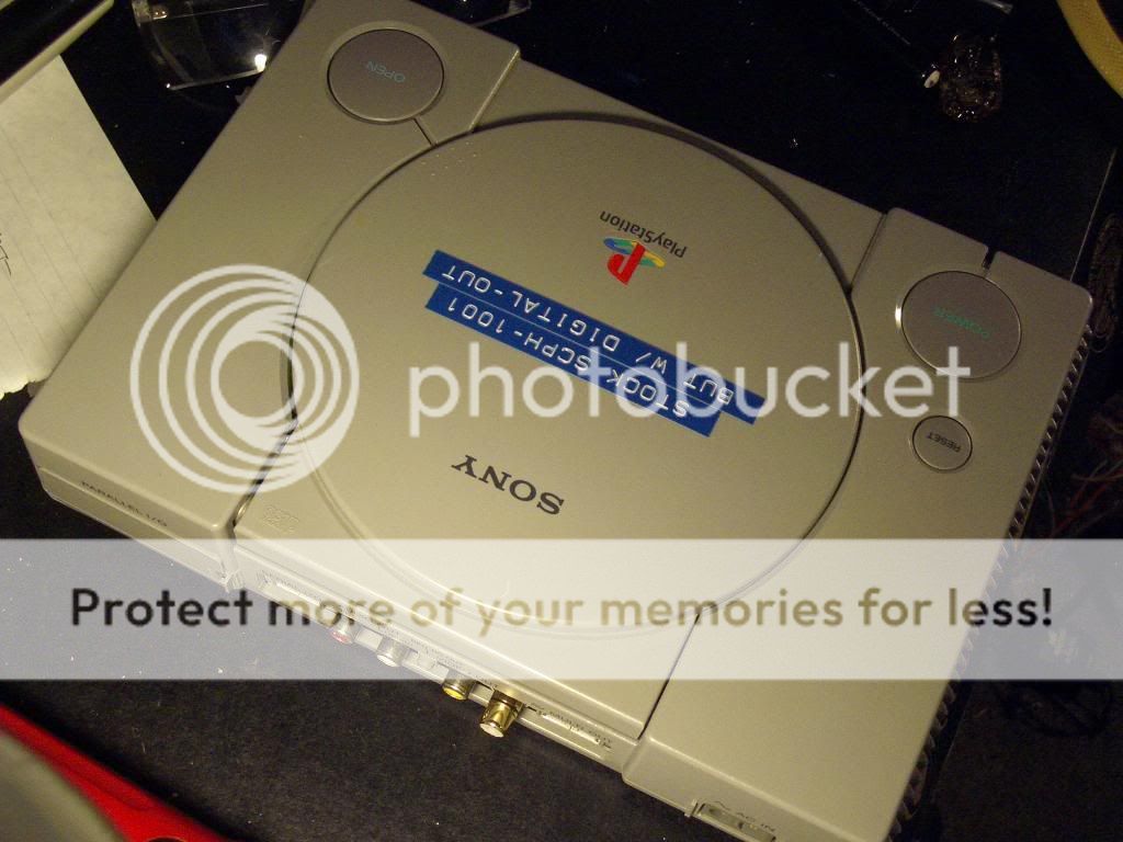
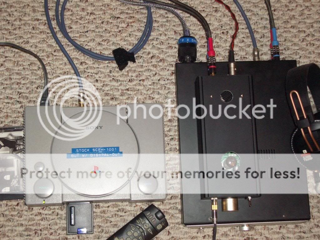
So here came my little experiment. I still have a stock SCPH-1001, which I don't mind adding a digital-output to it ("stock" means stock sound, no modification to the audio out). might as well use that. If the experiment goes wrong and kills board, I will only be out 10 ~15 bucks.
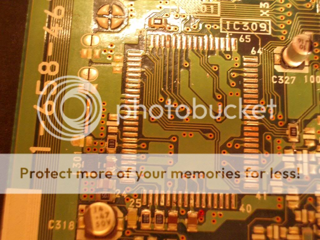
The first step is figure out how to get to pin60 and p59. I pulled the CXD2510Q off my "completely dead" 1001 board (long story short, the board got destroyed when I accidentally shorted the 7.6v line to the 3.6V during an all-linear external power supply upgrade), and looked at the trace under the chip. Pin 59/60 are not connected to anywhere. See photo. Signals will have to be tapped directly from the pins.
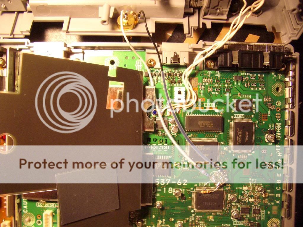
The next step is to lift the pins off the pad for easier access. I suppose you can solder wires directly to the pins but the chance of bridging is pretty high, so I chose to lift the pins. Pin 59/60 were carefully lifted up using a fine tip dental pick while the soldering iron tip was touch the pad. It can be done without magnification, though I did use a magnifier to check and make sure there is no solder bridge under the pin.
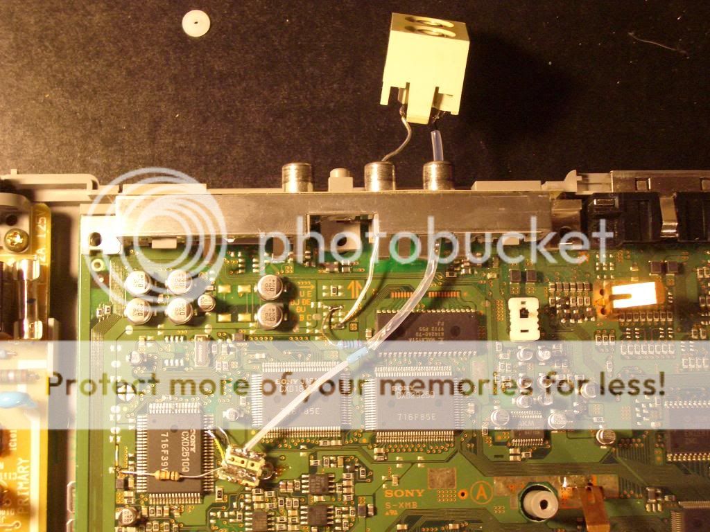
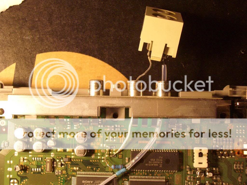
Now connect the wires to the pins. To prevent stressing the pins, I added a little pieced of perf board as anchor (there is a piece of wire coming up from the underside and soldered to two pads of the perf board, then the anchor wire is soldered to a large pad on the 1001 board), connected thin 28awg wires between the anchor board and the lifted pins.
piping the SPDIF signal out:
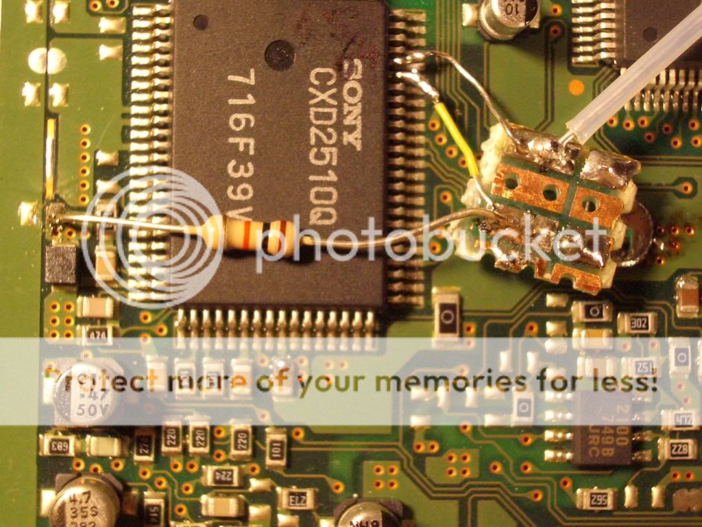
-- A 300 ohm resistor is soldered to the pad (on the anchor board) that links to pin60, the other end of this resistor goes to the center pin of digital-out RCA socket;
-- A 10k resistor is soldered to the pad that links to pin59, the other end of this resistor is soldered to the upper pad of L301 (left side of CXD2510Q), which is V+. This enables pin60's output.
-- A 100 ohm resistor is connected between the digital-out socket's center pin and the ground.
-- of course, the socket's barrel is connected to the ground.
Put everything back together, connect a digital cable to my little modded Zhaolu D2C DAC --> HCC86 hybrid amp --> Fostex T50rp headphones, and press "play" on the playstation remote........😱 😀 Music is playing.. And the sound is smooth, much smoother than the analog-out (yes, my modded D2C is smooth... 😀)
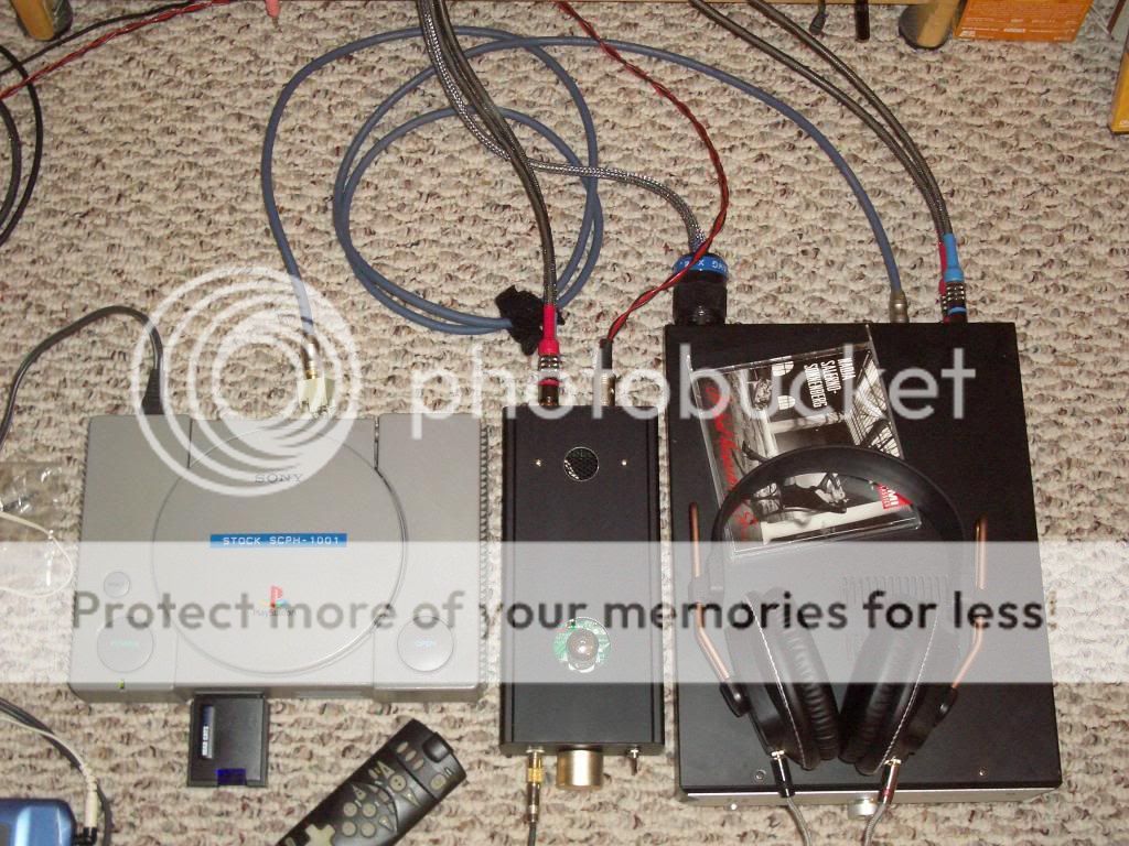
There we have it, folks, the PS1 digital-out mod. You only have to mess with two pins, add two pieces of thin wire, three resistors, one RCA socket and one ground wire. Simple as that😉 The playstations are cheap and plentiful, they are well built, reliable, laser adjustments are easily accessible. Not to mention a remote control can be added easily. What is not to like? Everybody should have at least one PS1 transport, don't you think? 😀
Now how about an Ubber PS1 CD transport? anybody? The spinning transport thingey can be easily mounted to a heavy block of something (wood, copper, granite, gold) and suspended via.... anything from rubber band to coil spring to magnetic levitation devices; use linear supply to provide power to the board (better yet, battery)..... come on, push the envelops, the sky is the limit 😀
Maybe there is a select pin in some chip upstream that can set Eiaj / I2s? Well, the research turned up nothing, I don't have a schematic and couldn't find datasheet for some of the chips.
And then there is this CXD2510Q chip in the upper left corner of the board. I downloaded the datasheet, and was looking at the pin out's. According to the datasheet, Pin#60 is "Dout", Pin#59 is the pin to enable it.
...
...
Dout?
hmmm, like the Dout pin in a CXD2500?
...
...
... somehow I remember somebody somewhere mentioned the Dout in the cxd2500 is SPDIF, maybe this 2510Q has spdif output as well?.....🙄
....
....
So here came my little experiment. I still have a stock SCPH-1001, which I don't mind adding a digital-output to it ("stock" means stock sound, no modification to the audio out). might as well use that. If the experiment goes wrong and kills board, I will only be out 10 ~15 bucks.
The first step is figure out how to get to pin60 and p59. I pulled the CXD2510Q off my "completely dead" 1001 board (long story short, the board got destroyed when I accidentally shorted the 7.6v line to the 3.6V during an all-linear external power supply upgrade), and looked at the trace under the chip. Pin 59/60 are not connected to anywhere. See photo. Signals will have to be tapped directly from the pins.
The next step is to lift the pins off the pad for easier access. I suppose you can solder wires directly to the pins but the chance of bridging is pretty high, so I chose to lift the pins. Pin 59/60 were carefully lifted up using a fine tip dental pick while the soldering iron tip was touch the pad. It can be done without magnification, though I did use a magnifier to check and make sure there is no solder bridge under the pin.
Now connect the wires to the pins. To prevent stressing the pins, I added a little pieced of perf board as anchor (there is a piece of wire coming up from the underside and soldered to two pads of the perf board, then the anchor wire is soldered to a large pad on the 1001 board), connected thin 28awg wires between the anchor board and the lifted pins.
piping the SPDIF signal out:
-- A 300 ohm resistor is soldered to the pad (on the anchor board) that links to pin60, the other end of this resistor goes to the center pin of digital-out RCA socket;
-- A 10k resistor is soldered to the pad that links to pin59, the other end of this resistor is soldered to the upper pad of L301 (left side of CXD2510Q), which is V+. This enables pin60's output.
-- A 100 ohm resistor is connected between the digital-out socket's center pin and the ground.
-- of course, the socket's barrel is connected to the ground.
Put everything back together, connect a digital cable to my little modded Zhaolu D2C DAC --> HCC86 hybrid amp --> Fostex T50rp headphones, and press "play" on the playstation remote........😱 😀 Music is playing.. And the sound is smooth, much smoother than the analog-out (yes, my modded D2C is smooth... 😀)
There we have it, folks, the PS1 digital-out mod. You only have to mess with two pins, add two pieces of thin wire, three resistors, one RCA socket and one ground wire. Simple as that😉 The playstations are cheap and plentiful, they are well built, reliable, laser adjustments are easily accessible. Not to mention a remote control can be added easily. What is not to like? Everybody should have at least one PS1 transport, don't you think? 😀
Now how about an Ubber PS1 CD transport? anybody? The spinning transport thingey can be easily mounted to a heavy block of something (wood, copper, granite, gold) and suspended via.... anything from rubber band to coil spring to magnetic levitation devices; use linear supply to provide power to the board (better yet, battery)..... come on, push the envelops, the sky is the limit 😀
Last edited:
Since it is proven working, might as well make it official and mount a solid RCA jack for the digital out....
There is only one good spot on the back of the 1001 for mounting the digital-out jack. on the inside there is a cavity that is about 10mm tall, whatever RCA socket I use will have to be small enough to fit into that cavity. I am using cheap connex "tiffiny style" jack which has two flat surfaces measured 10mm across, allowing it to barely fit in. Somehow partsconnexion claims they use 12mm mounting holes. If other "12mm" sockets are the similar to this one, then there are many other higher grade 12mm RCA jacks available for this mod. To me the cheap connex is good enough, come on, it is just digital-out, on a playstation, and it already looks sooooo much better than those three factory "white metal" RCA jacks ....
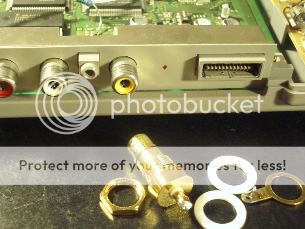
I used a 10mm drill bit to make the hole.
Note: since there is not enough room to use the ring/ground tab, the ground wire has to be soldered directly to the barrel (which draws a lot of heat so crank your soldering iron way up) before pushing the socket through the hole.
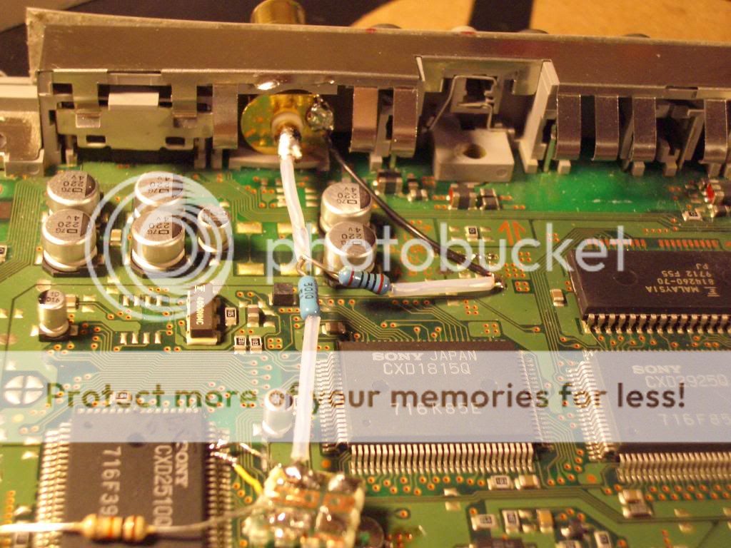
resistor value can be seen in the photo. Vertical resistor: 300 ohm, top horizontal resistor: 100 ohm. bottom horizontal resistor 10k.
Put everything back together again..... looks quite official now, doesn't it?
There is only one good spot on the back of the 1001 for mounting the digital-out jack. on the inside there is a cavity that is about 10mm tall, whatever RCA socket I use will have to be small enough to fit into that cavity. I am using cheap connex "tiffiny style" jack which has two flat surfaces measured 10mm across, allowing it to barely fit in. Somehow partsconnexion claims they use 12mm mounting holes. If other "12mm" sockets are the similar to this one, then there are many other higher grade 12mm RCA jacks available for this mod. To me the cheap connex is good enough, come on, it is just digital-out, on a playstation, and it already looks sooooo much better than those three factory "white metal" RCA jacks ....
I used a 10mm drill bit to make the hole.
Note: since there is not enough room to use the ring/ground tab, the ground wire has to be soldered directly to the barrel (which draws a lot of heat so crank your soldering iron way up) before pushing the socket through the hole.
resistor value can be seen in the photo. Vertical resistor: 300 ohm, top horizontal resistor: 100 ohm. bottom horizontal resistor 10k.
Put everything back together again..... looks quite official now, doesn't it?
^^^ the above digital-out mod is for SCPH-100x models, only. ^^^
v v v Now the SCPH-550X digital-out mod (work in progress): v v v
The 5501 apparently have a redesigned board and it doesn't use the 2510Q chip. Instead it has a CXD2545Q:
According to the datasheet, pin 71 is the Dout and pin 70 is the enable pin (high = enable).
I will do a signal tap later this weekend and see if Dout outputs SPDIF (it is supposedly possible for Sony to disable the pin function by firmware, need to see if Sony have done so or not).
Jacque has done something similar ; JACQUES HIFI PAGES spdif on oscilloscope and spdif from psx
He didn't like the Sony, but ymmv!
He didn't like the Sony, but ymmv!
Thanks for the link, Beacon, so it has been done before.....
To me, the reason for this kind of experiment is not just to add a function to the stock player. It opens the door to making a custom top-load transport, with mass dampening and clean power supply while keeping the cost at a reasonably low level. Like the Shigaraki clones, the mod group didn't just add a digital socket to the JVC boombox and call it good enough 😀 Maybe we can do something similar here. I suspect the sheet metal tray in the ps1 is holding back the sonic performance a bit.
Anyway, the 5501 mod is done and working. I don't think the 5501 is as good a mod candidate as the 1001, the chip is pretty far away from the back panel which requires using long signal wires, that can't be good for digital signal. The output socket has to be mounted to the top shell which makes disassembly a little trickier as well.
An externally hosted image should be here but it was not working when we last tested it.
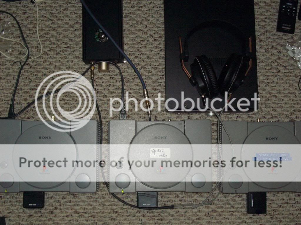
Comparison, 1001 vs. 5501, as CD transports (SPDIF out)
It is now possible to compare the sonic different of these "transports", since I have one each. They sound similar but not quite the same. The 1001 transport gives a slightly sharper sound with slightly larger stage; The 5501 transport is softer, darker, slightly more congested, more "mid-rangy", and a little more distant. The 5501 has a little more bass slam but the 1001 gives better bass detail. Overall I prefer the 1001 transport.
I then modded another 1001 and put it into the mix..... the two 1001 transports sound more or less the same, while the 5501 is a little different. Don't know whether the differences are caused by different process chips (2545Q has anti-shock function, the 2510Q doesn't) or simplely from using longer signal wires in the 5501.
Enjoy.
Last edited:
You're welcome, Audiocats. The fun is taking these mods in the direction you choose and I think the only limit is when you stop hearing any difference ;-). I've got a couple of modded 1001's and built on the work of a big PS1 fan, Michael Methe. His site is worth a visit, as he does everything really well!
Der CD Player
Der CD Player
Last edited:
I just checked a SCPH-101 (PSONE), the chip set is very different, don't know if it is possible to do a spdif tap.
looks like them went the long route to get the digital out of PS1....by tapping the Eiaj signal at the DAC then convert it to SPDIF?
I think the DIT4096 solution offers more scope for interfacing non-100x PSX's (and other consoles it seems)? Your solution is tailored for the 100x Playstation, so the alternative seems like overkill. (I didn't build a PSX transport, opting for Mick Feuerbacher's audio section mods instead). Are you considering installing a low jitter clock in your PSX? I'm not sure if it's practical but the DIT4096 datasheet indicates it needs MCLK (from the AKM DAC?) to work, so maybe there a improvements to be made here.
No plan on installing clock and such. My original intent was to find the I2S, and since I found the SPDIF instead I might add a CS8414 right next to the CXD2510Q and turn spdif into I2S and use the three RCA jacks in the back to send I2S signal out.
The reason of wanting to use I2S is that the signal frequency there is lower therefore has lower requirement on signal cabling. Also I don't think I2S has a minimum cable length requirement.
I think I have done everything I can, in modding the internal DAC section and the result is still not quite that great. The sound is smooth but not detailed enough for critical listening (smoother than my x555ES but not as detailed), I think the problem is with the AKM chip, there is not much to be done there.
Great work!
I was wondering if it is possible to add a digital input to the playstation. I say input as I think it would be great to be able to use an external transport (shigaclone) but still use the amazing dac in the playstation.
Thank you in advance
I was wondering if it is possible to add a digital input to the playstation. I say input as I think it would be great to be able to use an external transport (shigaclone) but still use the amazing dac in the playstation.
Thank you in advance
Not sure if it is worth the trouble using the PS1 board as a DAC. The chip itself has limited resolution, it seems. I would guess people like its sound because of the smoothness (the top end rolls off a bit so there is more or less no bit in the sound)
I think the bottle neck in the PS1 is the DAC chip, the transport section might have some potential.
I think the bottle neck in the PS1 is the DAC chip, the transport section might have some potential.
ah interesting ps1 mod .. i do some mick mods and happy , here is another mods .. i want to try it ... but looking ps1 spch 1001 is hard right now....
might the diy force be with you
might the diy force be with you
I can believe this thread has not been more popular!
I have modded my ps1 the same as Mick Feuerbacher. Great improvement might i say.
If i was to perform this digital out mod would it be able to be constantly on? as in would i have to have a switch so that the +v that activates the chip can be switched off when im using the internal dac part of the PlayStation in place of a external dac?
Thanks in advance
there is not interference between the SPDIF-out and the rest of the circuit. you simply gain the digital signal output, and lose nothing.
However..... the SPDIF-out doesn't have the mute function, it reports whatever signal the processor is sending out, ie. when you first install the CD and close the lid, there will be high pitch searching noise; if the playstation is on but not playing for a while (say, the CD ended and you didn't change CD or power down the station), the SPDIF will send out some kind of white noise signal. quite loud, scared me the first time .
I would recommand doing the mod to see how you like the sound quality of SPDIF out, I think it is quite good.
You can also tap the EIAJ signals from the processor and install a TDA1545A (NOS Dac chip) to replace the stock AK chip. Then you can use fancy resistors to do I/V for the 1545 output. I much prefer the TDA1545 to the stock AK chip, the NOS 1545 doesn't sound as resolved at first, but after a while it is hard to go back to the stock AK chip.
For some reason I just could not get the TDA1543A (the EIAJ version of TDA1543) to work in a ps-1001.
Hello all. I am tweak my ps1 for spdif and all works well.
BUT.. a have a some minor issue with sound.
More middle range, very light hight and low range. like from 500hz to 12khz 0db and 20-500hz and 12khz-20khz to -3-6db.
I think is all because output impendance of spdif not conformed.
I seen very similar issue (on analog) when input output impendace was wrong (like on input 47kohm device, but on 100kohm all been fine).
Can you explain why you use 300ohm and 100ohm in spdif output. Maybe for (R1xR2/)R1+R2=100x300/100+300=75Ohm standard digital output? )))
I think that output impendance been more greater or smaller then 75ohm what is a problem.
Maybe input impendance of my DAC are not standard.
Please explain why you use 100 and 300 ohm in this build, and how i can change nominals resistors to conform my dac impendance.
Thanks!
Last edited:
- Home
- Source & Line
- Digital Source
- Playstation 1 as CD transport (SPDIF output)