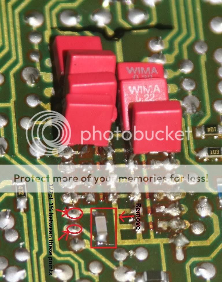
I would solder to the underside of the board as close to the pins as possible. Make sure you remove the original surface mount cap 1st!
I have attached directly to the pins previously but you run the risk of overheating the chip if you leave the heat on too long.
When you get round to the full clock based DEM solution, you will remove this cap and only feed the pins with the /4(/2) & Inverted /4(/2) of the clock as per the info previously provided...In the doc I parially wrote!!!! lol
I would solder to the underside of the board as close to the pins as possible. Make sure you remove the original surface mount cap 1st!
I have attached directly to the pins previously but you run the risk of overheating the chip if you leave the heat on too long.
When you get round to the full clock based DEM solution, you will remove this cap and only feed the pins with the /4(/2) & Inverted /4(/2) of the clock as per the info previously provided...In the doc I parially wrote!!!! lol
Ok, now I know
") *document securely saved since I first read through it*
*document securely saved since I first read through it*Thanks mate!
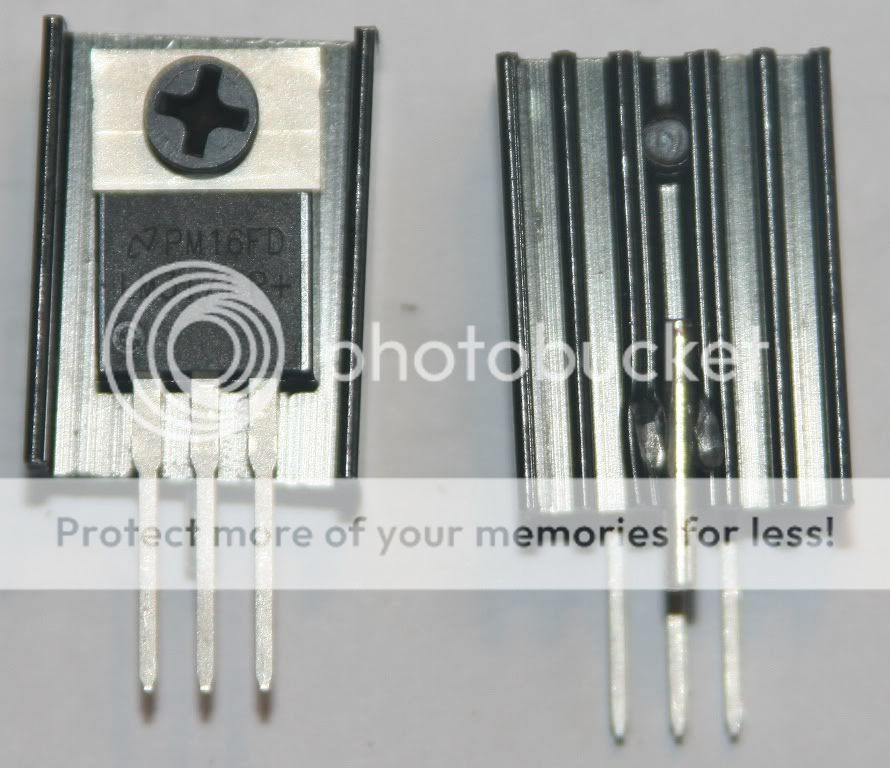
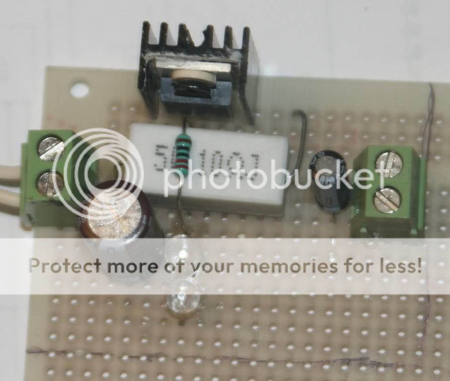
Will heatsinks w the following specs work for the SAA7220 regulator?
Or, slightly cheaper ones
Heatsink TO-220 / TO-218
34.5mm(W) x 63mm(H) x 12.5mm(D)
Thermal Resistance:6.8°C/W (H)
Aluminium , Black Anodised
Or, slightly cheaper ones
TV40, Compact twisted vane heatsink, pre-drilled to accomodate a single TO-220/TO218 package. Thermal Resistance: 9.9°C/W
BLACK ANODISED FINISH, WIDTH = 28mm, DEPTH = 38mm, HEIGHT = 22mm
Last edited:
Yep, that DEM cap goes there, not to sure about the heatsink but they both look ok to me.
Thanks Josh
PS for SAA7220(we'll see if the trafo works).
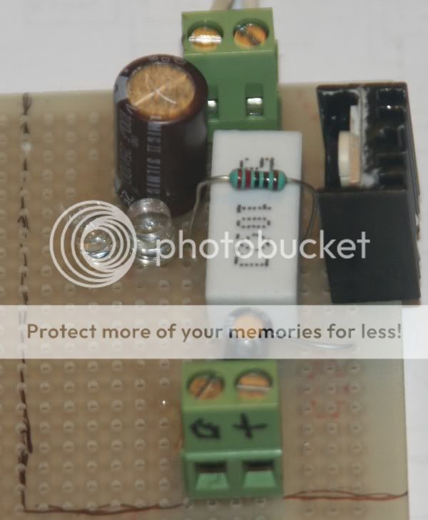
Components.
10R 5W
First Cap, 100uF/25V

Second Cap 10uF/50V
220R 0,6W 1%
LED Green, 2 in series
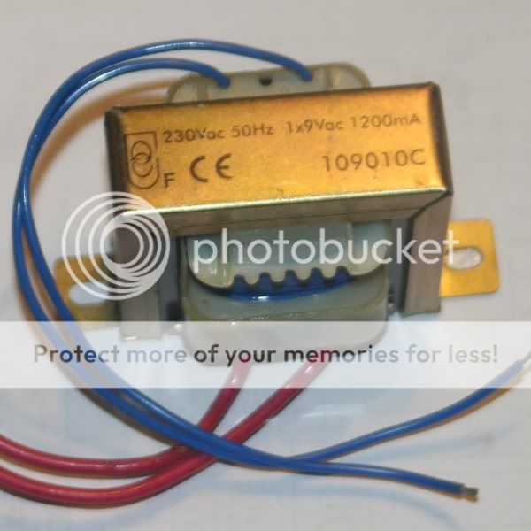
1x9Vac 1200mA
LM317T, will use other heatsinks though, maybe try with these to see how it sounds, I don't know
Also have TO-220 complete isolation kits.
Will solder the components on a veroboard.
Will feed it from either a regulator set to 10V or add a diode bridge(BYV95A) before 10R and GND
An externally hosted image should be here but it was not working when we last tested it.
Components.
10R 5W
An externally hosted image should be here but it was not working when we last tested it.
First Cap, 100uF/25V
Second Cap 10uF/50V
An externally hosted image should be here but it was not working when we last tested it.
220R 0,6W 1%
An externally hosted image should be here but it was not working when we last tested it.
LED Green, 2 in series
An externally hosted image should be here but it was not working when we last tested it.
1x9Vac 1200mA
LM317T, will use other heatsinks though, maybe try with these to see how it sounds, I don't know
Also have TO-220 complete isolation kits.
Will solder the components on a veroboard.
Will feed it from either a regulator set to 10V or add a diode bridge(BYV95A) before 10R and GND
Last edited:
I'm sure I've already said this but you shouldnt use the 10r resistor. It will only serve to restrict the supply. You also don't need 2 regulators on the same supply. Just use the 317 with the 2 LEDs on it's own. It will be fine. The more you put in line, the more you will effect performance
I'm sure I've already said this but you shouldnt use the 10r resistor. It will only serve to restrict the supply. You also don't need 2 regulators on the same supply. Just use the 317 with the 2 LEDs on it's own. It will be fine. The more you put in line, the more you will effect performance
Ok
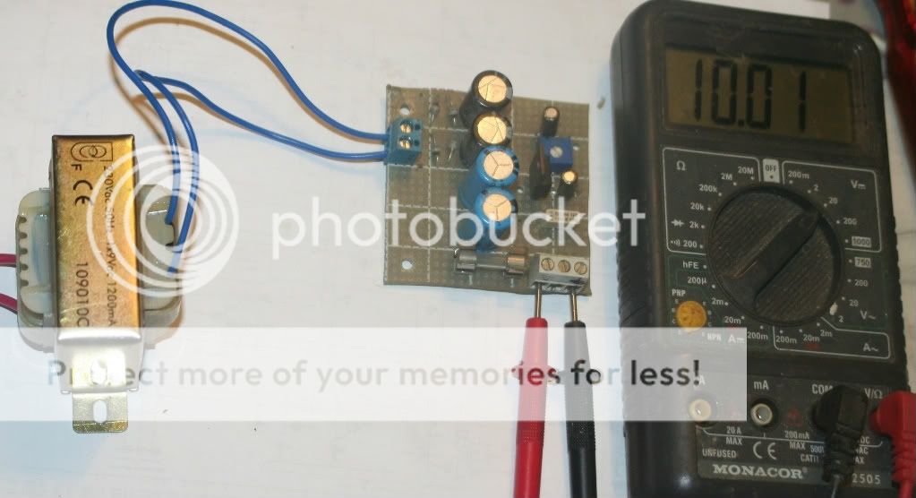
I tried it w the 10R and the regulator as per the the pic above, Somehow it gave me 7,40-7,41Vdc(no load)? What to change, except for what you stated above?
Last edited:
The 10r won't drop the voltage. It's the voltage after the LEDs that govern the output. You need to add a load to the supply to test it. Something like 100r to gnd will load 5v 50mA. This will be enough to check the reg output voltage under load. The current through the resistor will be 0.25w so it may get a little warm if you leave it on there too long!!! good exercise in ohms law V = I x R and P = I x V
If the reg op voltage is still too high, go to 1 led and measure to see what happens. The add 3 to see what heppens. You'll learn something about the reg!!!
good exercise in ohms law V = I x R and P = I x VIf the reg op voltage is still too high, go to 1 led and measure to see what happens. The add 3 to see what heppens. You'll learn something about the reg!!!
The 10r won't drop the voltage. It's the voltage after the LEDs that govern the output. You need to add a load to the supply to test it. Something like 100r to gnd will load 5v 50mA. This will be enough to check the reg output voltage under load. The current through the resistor will be 0.25w so it may get a little warm if you leave it on there too long!!!
If the reg op voltage is still too high, go to 1 led and measure to see what happens. The add 3 to see what heppens. You'll learn something about the reg!!!
I'll try with a 100R load and see what I get.
I'll also remove the 10R.
Thanks for being a BIG help!
100R gave me 3,8Vdc. Before I found a 100R, I tried 110R which gave me 4,07Vdc.
BUT, this is still hooked up to the other regulator...which gave just above 5Vdc when I measured across input on the LED reg. This is w load, w-out load I got 10Vdc pre 100R and 7,4 across output(plus LED's lit up, which they don't w the load)..
BUT, this is still hooked up to the other regulator...which gave just above 5Vdc when I measured across input on the LED reg. This is w load, w-out load I got 10Vdc pre 100R and 7,4 across output(plus LED's lit up, which they don't w the load)..
The 10r won't drop the voltage. It's the voltage after the LEDs that govern the output. You need to add a load to the supply to test it. Something like 100r to gnd will load 5v 50mA. This will be enough to check the reg output voltage under load. The current through the resistor will be 0.25w so it may get a little warm if you leave it on there too long!!!
If the reg op voltage is still too high, go to 1 led and measure to see what happens. The add 3 to see what heppens. You'll learn something about the reg!!!
I'd like to be able to experiment, but being on a tight budget I can't afford more parts at the moment(risk braking parts).
Unloaded just gave 13.53Vdc across input and 7.44Vdc across outputs.
This is w just rectifying between transformer and PS.
- Status
- This old topic is closed. If you want to reopen this topic, contact a moderator using the "Report Post" button.
- Home
- Source & Line
- Digital Source
- Marantz CD-50 and CD-60, TDA1541, CDM4/19