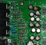
That's easy. All the small transistors in the left part of the picture, by the connectors are the mutting. The bottom 3+3 are for the two-channel (easy, look on the connectors on the back).I give up where's the 2 channel muting transistors but great capacitors pics folks
Actually the firs two towards the OpAmp are the "classical" mutting, the last one is for zero-digital-mutting.
It is not worth it, regardless what others think they heard, it is just wishfull thinking. People do it because is easyer to destroy than repair, it doesn't require any skills (like replacing the OpAmps).
Attachments
Last edited:
Some Pictures to Clarify, Folks. Couldn´t send them in PMs...
Hope this helps.
Tool used: hot air soldering station
After my reset of the laser pickup for CDs, it is still working!! (more than a year....)
Cheers,
Marcelo
Hope this helps.
Tool used: hot air soldering station
After my reset of the laser pickup for CDs, it is still working!! (more than a year....)
Cheers,
Marcelo
Attachments
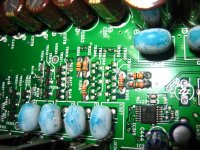
That's easy. All the small transistors in the left part of the picture, by the connectors are the mutting. The bottom 3+3 are for the two-channel (easy, look on the connectors on the back).
Actually the firs two towards the OpAmp are the "classical" mutting, the last one is for zero-digital-mutting.
It is not worth it, regardless what others think they heard, it is just wishfull thinking. People do it because is easyer to destroy than repair, it doesn't require any skills (like replacing the OpAmps).
I might try the opamps just still unsure if i need 8 of one kind and such silly confusions
Emmbee - There are in the Audio Board.... unter the video one. Seen from the back of the Player: Left-down ... follow the audio connections inside. see pic..
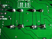
Smallies - YEAH! (Please put those Caps out of the equation too!!!!) See my shunt dirty work.
Smallies - YEAH! (Please put those Caps out of the equation too!!!!) See my shunt dirty work.
Attachments
I know this is an Old Thread
I know this is an old tread but was wondering if there was still any interest in Modifying the Denon 2910 ?
I recently bought one in Silver to go with my stereo and can't say that I love the sound its good but seems it could be better. I had a 2900 and it seemed to sound better stock. That dies a while back wish I had kept and fixed it but its gone. Anyway I was reading this thread and not sure I could do these modes without a schematic and that also there are lots of ideas here so its hard to pin point the best most important mods that I could or should do that don't require to much work.
Let me know if someone has interest in this still ?
Help With Denon 2910 Mod or Clarification of this Post
Hoping to get some help and clarification on this Denon 2910 Mod
I have been looking at the whole post and would like to do this but the post goes all over the place and never says what to remove or by pass so looking for some help.
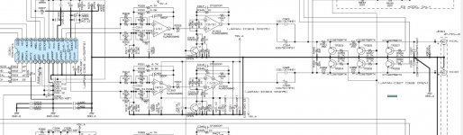
So I will break this down and add a schematic to look at and someone can maybe help my get this done here is the original post
Very simple, OPs changed to LM4562 I/V (way more warmth and detail at the same time!), output buffers changed to LM4562, LM49723 and OPA1642 in each player, muting transistors taken away, Output Condensers taken away, and shunted one of two output resistors, leaving 150 ohm in series.
All players in general are seriously impaired in the analog output stage (low cost parts), I know they can't leave a product without an output condenser, for instance, but as single mod it is to shunt it, im not aware of a bigger and cheapest mod.
(OPs changed to LM4562)
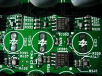
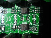
OK I assume he is talking about IC302 and IC 303
(Output buffers changed to LM4562, LM49723 and OPA1642)
Is this the same thing? Talking about the Op Amps?
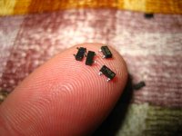
(Muting transistors taken away)
Ok I did this no problem seemed to maybe help the highs a bit. I assumed we are talking about TR 303 thru 308
(Output Condensers taken away)
No Idea what he is talking about here is this a capacitor or capacitors that are being removed and then are they just removed or jumpered across? Is this C327 and C328 or C323 324 325 & 326? I wished he had added the numbers from the schematic.
(Shunted one of two output resistors, leaving 150 ohm in series.)
I assume we are talking about R351 & R352 Or R355 & R356 so you put a jumper across were they were is that what he means by shunted?
So R 349 & R 350 need to stay?
Ok this is a start of what I need there were many questions by people in this post that were never answered and the post went in a whole new direction going into power supply stuff that I don’t want to do so if someone could look at the pics and help me out that would be great
Hoping to get some help and clarification on this Denon 2910 Mod
I have been looking at the whole post and would like to do this but the post goes all over the place and never says what to remove or by pass so looking for some help.
So I will break this down and add a schematic to look at and someone can maybe help my get this done here is the original post
Very simple, OPs changed to LM4562 I/V (way more warmth and detail at the same time!), output buffers changed to LM4562, LM49723 and OPA1642 in each player, muting transistors taken away, Output Condensers taken away, and shunted one of two output resistors, leaving 150 ohm in series.
All players in general are seriously impaired in the analog output stage (low cost parts), I know they can't leave a product without an output condenser, for instance, but as single mod it is to shunt it, im not aware of a bigger and cheapest mod.
(OPs changed to LM4562)
OK I assume he is talking about IC302 and IC 303
(Output buffers changed to LM4562, LM49723 and OPA1642)
Is this the same thing? Talking about the Op Amps?
(Muting transistors taken away)
Ok I did this no problem seemed to maybe help the highs a bit. I assumed we are talking about TR 303 thru 308
(Output Condensers taken away)
No Idea what he is talking about here is this a capacitor or capacitors that are being removed and then are they just removed or jumpered across? Is this C327 and C328 or C323 324 325 & 326? I wished he had added the numbers from the schematic.
(Shunted one of two output resistors, leaving 150 ohm in series.)
I assume we are talking about R351 & R352 Or R355 & R356 so you put a jumper across were they were is that what he means by shunted?
So R 349 & R 350 need to stay?
Ok this is a start of what I need there were many questions by people in this post that were never answered and the post went in a whole new direction going into power supply stuff that I don’t want to do so if someone could look at the pics and help me out that would be great
Attachments
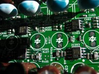
Ok being I didn't get any feedback on this I went ahead as I saw fit. I changed the IC 302 and 303 to LM 4562s and removed the muting resistors I didn't change the two capacitors C323 324 325 and 326 in the audio path though I think I should and or will.
Results the presence of the player is better and highs are clearer. So yes this does make it better than it was. without the mutting resistors you get a very light click in the system when you turn on the machine and once in a while like when you put in a disc . not hardly noticeable at all . Sound is better I ordered the output from TI and they were cheap a few bucks .
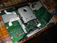
I also removed the whole video card being I don't use this as a DVD player and its easy to remove not sure if this helped the sound but I found no need to have it. So the Denon 2910 is now just a CD / SACD player .
Results the presence of the player is better and highs are clearer. So yes this does make it better than it was. without the mutting resistors you get a very light click in the system when you turn on the machine and once in a while like when you put in a disc . not hardly noticeable at all . Sound is better I ordered the output from TI and they were cheap a few bucks .
I also removed the whole video card being I don't use this as a DVD player and its easy to remove not sure if this helped the sound but I found no need to have it. So the Denon 2910 is now just a CD / SACD player .
- Home
- Source & Line
- Digital Source
- Denon DVD-2910 mods