Another Shiga clone alternative?
I recently asked if the JVC EZ38 boombox could be used for a Shiga clone hack, but got no reply. Further investigation shows that the EZ38 boombox uses the Philips SAA7824HL DSP chip. The data sheet for this chip indicates that it is capable of providing output to an external DAC. It looks like there are several options for data output, but what's the right one for sp/dif? And how would it be configured? I'm kind of in over my head here, and am looking for any help I can get.
Here are a few pages from the SAA7824 data sheet and a copy of the EZ38 service manual. The complete SAA7824 data sheet can be accessed here:
SAA7824HL pdf, SAA7824HL description, SAA7824HL datasheets, SAA7824HL view ::: ALLDATASHEET :::
Attachments
Rudy,
To make a Shigaclone you need to look for a boombox with following chips:
- LA9242 for ASP - analog signal processor
- LC78601 for DSP - digital signal processor
- LA6541 for motor driver
- SFP101N-15P or 16P for CD mechanic
At some point in time Sanyo had a great engineering team who designed LA924X & LC7860X combo. With careful implementation these chips make one of the best CD transport.
Regards,
Tibi
I’ve wanted to build a Shigaclone for quite a while now.
Of course, like many things, I discovered this thread a little too late. Like a lot of others who wanted to build a Shigaclone, it just seemed impossible to find the JVC box it was based on.
Shigaclone II came along, and it seemed like a great idea, but it was a lot different than pulling the trigger on a $50 boom box to have some fun and try to build something cool.
I was struggling trying to get my old Rotel 855 to play again, and even tried replacing it with another 855 I found on eBay...only to be disappointed with a different set of problems.
I had resigned myself to an old NEC player that I found for about $30 at a thrift store.
Then one day not that long ago I was cruising the Swap Meet and there it was...the guts from a RC-EZ51H.
So here I am, 10 years after Shigaclone was breaking news, trying to build one.
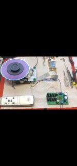
I only just pulled the parts out of the box the other day. I’ve posted some pics of my progress so far.
First up...just trying to see if the parts work by figuring out some sort of 8 volt power supply. At first I tried a 9V wallwort...dug out of the tangled “will not throw out” drawer...not enough juice. Once it was connected, it wouldn’t spin properly or read a table of contents.
I happened to have an unused mosfet regulator board that was designed for one of RJMs headphone amps. I hooked up a 12V wallwort to it and Voila!...it fired right up.
After that I tried building a supply out of a Triad VPT24-1040 and GBPC3504 that I have on hand, but the voltage was way too high going in and out of the mosfet reg board. I tried a few different bridges and checked wiring on the dual primaries and secondaries, but couldn’t get less than 18V after the bridge and 14V after the regulator with my mains supply.
I don’t have any LM7808 on hand, so for now I’ll be running the mosfet regulator fed by a 12V SMPS laptop supply I found in my stash.
So, no modifications at all so far. It’s up and working...even the remote.
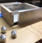
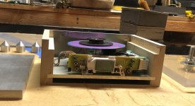
I’ve moved on to fabrication of a chassis for it. I don’t have any Copper plate around. I do have plenty of aluminum that I buy at a scrap barn from a local supplier. Also some Lexan and my usual choice of Maple.
I’ve tried to come up with something that will be solid and also have a good damping characteristic for any vibration the transport creates or experiences. To that end, I used a trick (granular damping) I also employed in my turntable build by adding a false floor in the bottom of the chassis to create a cavity that will be filled with lead shot.
The top plate of the chassis is made of 9/16” thick Lexan that will be machined so the CD sits recessed below the top surface so a cover can be made to keep dust and the like out.
The deck for mounting the transport is 1/4” aluminum plate. The faceplate at 3/8” adds even more mass and will allow me to mill pockets for the display and buttons.
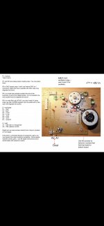
My first technical question is about the output resistors. They seem a matter of taste, but Peter recommended Dale 100/300R. A pdf I found says 75/75R. I’m not sure what I have on hand. If I have the 100/300R I would try that first. Can someone confirm which of the resistors is supposed to be 100 and which is 300? I’ve attached an image from the pdf with them labeled as “A1” and “A2”.
Thanks in advance for any feedback.
Of course, like many things, I discovered this thread a little too late. Like a lot of others who wanted to build a Shigaclone, it just seemed impossible to find the JVC box it was based on.
Shigaclone II came along, and it seemed like a great idea, but it was a lot different than pulling the trigger on a $50 boom box to have some fun and try to build something cool.
I was struggling trying to get my old Rotel 855 to play again, and even tried replacing it with another 855 I found on eBay...only to be disappointed with a different set of problems.
I had resigned myself to an old NEC player that I found for about $30 at a thrift store.
Then one day not that long ago I was cruising the Swap Meet and there it was...the guts from a RC-EZ51H.
So here I am, 10 years after Shigaclone was breaking news, trying to build one.
I only just pulled the parts out of the box the other day. I’ve posted some pics of my progress so far.
First up...just trying to see if the parts work by figuring out some sort of 8 volt power supply. At first I tried a 9V wallwort...dug out of the tangled “will not throw out” drawer...not enough juice. Once it was connected, it wouldn’t spin properly or read a table of contents.
I happened to have an unused mosfet regulator board that was designed for one of RJMs headphone amps. I hooked up a 12V wallwort to it and Voila!...it fired right up.
After that I tried building a supply out of a Triad VPT24-1040 and GBPC3504 that I have on hand, but the voltage was way too high going in and out of the mosfet reg board. I tried a few different bridges and checked wiring on the dual primaries and secondaries, but couldn’t get less than 18V after the bridge and 14V after the regulator with my mains supply.
I don’t have any LM7808 on hand, so for now I’ll be running the mosfet regulator fed by a 12V SMPS laptop supply I found in my stash.
So, no modifications at all so far. It’s up and working...even the remote.
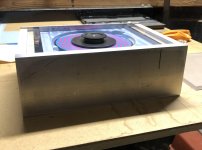
I’ve moved on to fabrication of a chassis for it. I don’t have any Copper plate around. I do have plenty of aluminum that I buy at a scrap barn from a local supplier. Also some Lexan and my usual choice of Maple.
I’ve tried to come up with something that will be solid and also have a good damping characteristic for any vibration the transport creates or experiences. To that end, I used a trick (granular damping) I also employed in my turntable build by adding a false floor in the bottom of the chassis to create a cavity that will be filled with lead shot.
The top plate of the chassis is made of 9/16” thick Lexan that will be machined so the CD sits recessed below the top surface so a cover can be made to keep dust and the like out.
The deck for mounting the transport is 1/4” aluminum plate. The faceplate at 3/8” adds even more mass and will allow me to mill pockets for the display and buttons.
My first technical question is about the output resistors. They seem a matter of taste, but Peter recommended Dale 100/300R. A pdf I found says 75/75R. I’m not sure what I have on hand. If I have the 100/300R I would try that first. Can someone confirm which of the resistors is supposed to be 100 and which is 300? I’ve attached an image from the pdf with them labeled as “A1” and “A2”.
Thanks in advance for any feedback.
Attachments
-
 3F56CEDC-8C52-4BD6-A6F6-4FC4635750F2.jpg139.6 KB · Views: 561
 -
 D33F17C3-C8E6-4C33-B9D5-FE2AB91214F5.jpeg601 KB · Views: 520
 -
 91D8DEE6-A436-415E-9979-DE5A13191544.jpg445.7 KB · Views: 511
 -
 1939D94E-5658-4F26-B374-DA0C638B5574.jpg592.8 KB · Views: 535
 -
 0F03B6D8-BCDD-4594-BCB7-35B30F3EA8B2.jpg152 KB · Views: 570
I admire your effort to build your own CD transport.
Unfortunately, RC-EZ51H have none of the required parts to make a Shigaclone.
I have attached RC-EZ51H service manual.
I suggest you to look for a second hand Shiga MKII.
Regards,
Tibi
Unfortunately, RC-EZ51H have none of the required parts to make a Shigaclone.
I have attached RC-EZ51H service manual.
I suggest you to look for a second hand Shiga MKII.
Regards,
Tibi
Attachments
Hi Tivcol
Your post gave me a scare. First, I said “How can I be so dumb to believe what others post and believe this player is the right one?”...then I re-tracked my research.
You have said this before...specifically, in this thread in post #7986:
“ With JVC RC-EZ51H you'll not get a Shigaclone. JVC RC-EZ51H make use of LC78690 instead of LC78601 and LA9242.
To get a Shigaclone you need these two chips. For DSP LC78601 and for ASP LA9242.
What make Shigaclone to sound so good are these two chips: LC78601 and LA9242. I have tested several LC786XX successors and none is even closer to LC78601.
Regards,
Tibi
PS: You may download JVC RC-EZ51H schematic from here Az oldal nem talalhato! - Page not Found! | Elektrotanya
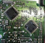
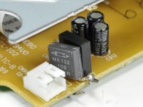
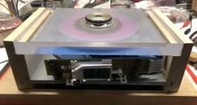
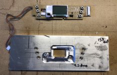
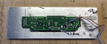
I have attached a picture of the back side of my transport with the IC mounted.
This machine came as guts to me with the original manual, remote etc. It is as far as I know a JVC EZ51H as the manual is labeled.
This transport has the exact chips mounted on its circuit board that you are saying would make it a Shigaclone equivalent.
LC78601R and LA9242 is the exact printing on the chips.
Perhaps there was a change during the production run of this player and it was never noted in the service manuals.
Your post gave me a scare. First, I said “How can I be so dumb to believe what others post and believe this player is the right one?”...then I re-tracked my research.
You have said this before...specifically, in this thread in post #7986:
“ With JVC RC-EZ51H you'll not get a Shigaclone. JVC RC-EZ51H make use of LC78690 instead of LC78601 and LA9242.
To get a Shigaclone you need these two chips. For DSP LC78601 and for ASP LA9242.
What make Shigaclone to sound so good are these two chips: LC78601 and LA9242. I have tested several LC786XX successors and none is even closer to LC78601.
Regards,
Tibi
PS: You may download JVC RC-EZ51H schematic from here Az oldal nem talalhato! - Page not Found! | Elektrotanya
I have attached a picture of the back side of my transport with the IC mounted.
This machine came as guts to me with the original manual, remote etc. It is as far as I know a JVC EZ51H as the manual is labeled.
This transport has the exact chips mounted on its circuit board that you are saying would make it a Shigaclone equivalent.
LC78601R and LA9242 is the exact printing on the chips.
Perhaps there was a change during the production run of this player and it was never noted in the service manuals.
Attachments
Thank you for your replay.
As long your board have these two chips you can enjoy a Shigaclone.")
I do not why there is such difference between your player and service manual, but is good to know that there is one that others may look for and build such a great player.
Regards,
Tibi
As long your board have these two chips you can enjoy a Shigaclone.
I do not why there is such difference between your player and service manual, but is good to know that there is one that others may look for and build such a great player.
Regards,
Tibi
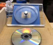
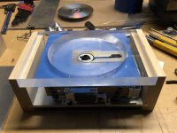
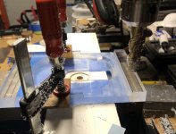
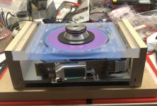
Thanks! Here are some more pictures of my progress. I spent the afternoon yesterday machining the top disk tray. It’s not completely done.
I appear to have answered my own question about the resistors...Peter posted a picture at the beginning of his CD Transport thread showing a 100R Caddock resistor in the “A2” position labeled in the board picture I posted.
I appear to have answered my own question about the resistors...Peter posted a picture at the beginning of his CD Transport thread showing a 100R Caddock resistor in the “A2” position labeled in the board picture I posted.
Attachments
Like Chromenuts I have admired this thread from afar for a long time and the lockdown presented a perfect opportunity to dive in.
I acquired an EZ51 and assembled it on the trusty block of wood - removed the choke and R5 and exchanged E5 with a 470uF cap. Soldered the jumper, joined the red/black wires to a switch and away it goes.
Initially powered using the box transformer/LM317.Then I tried an R-Core 30VA 16v/9v with better results but the LM317 needed a big heatsink for the drop down from 16v - so have ordered an LM2940 and will see if that provides enough current.
Last edited:
Very nice - love the simplicity of it.
Don't forget the mods to replace the smd components around the laser - it is NOT an easy job but you will get the biggest gains in audio quality compared to any other mods for Shigaclone.
Don't forget the mods to replace the smd components around the laser - it is NOT an easy job but you will get the biggest gains in audio quality compared to any other mods for Shigaclone.
Thanks! Here are some more pictures of my progress. I spent the afternoon yesterday machining the top disk tray. It’s not completely done.
I appear to have answered my own question about the resistors...Peter posted a picture at the beginning of his CD Transport thread showing a 100R Caddock resistor in the “A2” position labeled in the board picture I posted.
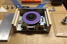
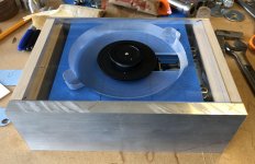
I’ve gotten a bit hung up on the design of the transport. Made some progress. Mostly machining the tray and related.
Had to make some finger pockets to be able to get discs in and out. It was still difficult to hold them with the deep pockets.
I had decided I wanted some sort of cover. I roughed out a 1/4” Lexan cover.
I then decided I’d rather the cover was flush with the top of the faceplate when it was in place. I machined the tray down to receive the cover and that improved placement and removal of discs drastically.
All along, this is a balancing act trying to keep the disc at the right height to clear the tray and cover as well as have the mechanism clearance below the tray.
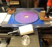
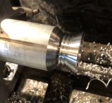
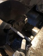
To complicate things further, I wasn’t thrilled with the clamp puck aesthetics, so I decided to try and improve them and give myself a better grip.
Didn’t want to start from scratch, or give up the magnetic clamp, so I tried machining a slip over solution.
It looked fine on the lathe...it’s good for .001 concentricity. Had a few blunders towards the end I had to fix.
Unfortunately, it didn’t perfectly center on the original puck when I attached it I think. I had to play with clocking its orientation to get it to spin on center better. It may partly be the small recess I created on the top so I could see rotation. I may take another shot at a different puck assembly.
The top of the puck is supposed to protrude through the cover when it’s done. Need to figure that and a cover handle out.
Had to make some finger pockets to be able to get discs in and out. It was still difficult to hold them with the deep pockets.
I had decided I wanted some sort of cover. I roughed out a 1/4” Lexan cover.
I then decided I’d rather the cover was flush with the top of the faceplate when it was in place. I machined the tray down to receive the cover and that improved placement and removal of discs drastically.
All along, this is a balancing act trying to keep the disc at the right height to clear the tray and cover as well as have the mechanism clearance below the tray.
To complicate things further, I wasn’t thrilled with the clamp puck aesthetics, so I decided to try and improve them and give myself a better grip.
Didn’t want to start from scratch, or give up the magnetic clamp, so I tried machining a slip over solution.
It looked fine on the lathe...it’s good for .001 concentricity. Had a few blunders towards the end I had to fix.
Unfortunately, it didn’t perfectly center on the original puck when I attached it I think. I had to play with clocking its orientation to get it to spin on center better. It may partly be the small recess I created on the top so I could see rotation. I may take another shot at a different puck assembly.
The top of the puck is supposed to protrude through the cover when it’s done. Need to figure that and a cover handle out.
Attachments
-
 9A15DC2E-FB92-4001-8BE3-BA1EA2DCA02C.jpg685.9 KB · Views: 522
 -
 4264E22D-0539-4DEA-8426-CDD3722B1FC3.jpg551.4 KB · Views: 163
 -
 8F1E6E8B-AD10-47D3-821F-088A0C3565B0.jpeg597.6 KB · Views: 165
 -
 774CBFF7-0D65-4237-951F-5A28B21CC63B.jpg461.6 KB · Views: 187
 -
 340BCFC8-14A3-4061-BC10-EA95ACEBBFB7.jpeg661 KB · Views: 221
 -
 CC1C509A-0420-40AC-9149-6DEDA54534C7.jpeg755.5 KB · Views: 197
Last edited:
Very nice - love the simplicity of it.
Don't forget the mods to replace the smd components around the laser - it is NOT an easy job but you will get the biggest gains in audio quality compared to any other mods for Shigaclone.
I’m not sure if those mods were included in that pdf I found documenting more elaborate changes than the basic ones Peter outlines in his transport building thread. I will be doing the basics to begin with.
Here is a pdf
Since this was written I think some of the recommended caps have changed
Recommended now on laser pins is Vishay MKP-1837 parallel with 1000pf silver mica
On the green tape where the pdf says Arcotronics use the same MKP-1837 as laser
Also bypass trim pot with 1000pf silver mica.
Cover everything with hot glue.
Also you can add 1uf film cap across pins of spindle motor - I use a Russian PIOs in this position
As I said the job is a bit tricky - working on the laser pins is relatively easy as is the trim pot - so do those and test before continuing. You have to position the caps carefully so they pass under and do bump the end of the laser tray.
Replacing the smd caps on the green tape is not easy (I have had to buy additional sf101p lasers because I have messed this up). Take care not to apply too much heat else the trace/tabs come off. I have found crimping the end of the lead to make it flat rather than round can help.
As I said previous the difference between unmodded and modded is like night and day.
I’m not sure if those mods were included in that pdf I found documenting more elaborate changes than the basic ones Peter outlines in his transport building thread. I will be doing the basics to begin with.
Attachments
Last edited:
@tomw...Thanks for the encouragement...the building is really my thing.
@sthcoaster...Thank you for that information. I’m not sure if it’s something I can tackle with my vision and clumsy soldering...but who knows? After reading your post I did some poking around and ordered some replacement laser assemblies for good measure. I figured they where cheap enough to have a couple of backups either way.
I’ve been kind of busy as we are making arrangements to have some overdue work done on the outside of the house.
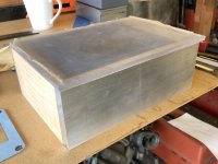
I did manage to rework the puck. I reduced the handgrip height and changed the hardware attaching it to the original so it is centered and spinning very concentric now.
I also roughed out a cover for the disc tray that allows the top of the puck grip to poke through. Still have to decide if I want to or can hinge it or not.
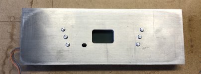
I moved on to the face plate. Machined out the back for the display and buttons after laying them out as best I could from measurements I took with my calipers.
I have it all roughed out with the display board trimmed down and mounts in place. I even managed to make up the buttons and got them in place and working.
Moving on to some partial assembly and other case work now.
@sthcoaster...Thank you for that information. I’m not sure if it’s something I can tackle with my vision and clumsy soldering...but who knows? After reading your post I did some poking around and ordered some replacement laser assemblies for good measure. I figured they where cheap enough to have a couple of backups either way.
I’ve been kind of busy as we are making arrangements to have some overdue work done on the outside of the house.
I did manage to rework the puck. I reduced the handgrip height and changed the hardware attaching it to the original so it is centered and spinning very concentric now.
I also roughed out a cover for the disc tray that allows the top of the puck grip to poke through. Still have to decide if I want to or can hinge it or not.
I moved on to the face plate. Machined out the back for the display and buttons after laying them out as best I could from measurements I took with my calipers.
I have it all roughed out with the display board trimmed down and mounts in place. I even managed to make up the buttons and got them in place and working.
Moving on to some partial assembly and other case work now.
Attachments
-
 9BA78642-36F8-49BD-8166-AD8580107189.jpg545.3 KB · Views: 226
 -
 886FA8C5-6AC1-492E-A123-E0CA0C9B97C7.jpg996.1 KB · Views: 229
 -
 B3DEA9FA-1B78-4503-9115-096B411DAB6F.jpg659.5 KB · Views: 231
 -
 84E17AAC-E8A1-4A99-93AD-7C0826E44C56.jpg515 KB · Views: 200
 -
 2DA2FA69-7547-4900-B1AF-0ECC4EF440F7.jpeg971.6 KB · Views: 204
Hello everyone,
I am glad that the Shiga story is still alive and there are many great machines born
I have been out of participating very long time and during that period I developed the ,fourth ,fifth ,ohh ,I don't relly know ,which iteration of the transport.
In short ,the most natural sounding...
Organic Z Audio - Bamboo sticks - roller bearing supported cd transport lens assembly | Facebook
- Home
- Source & Line
- Digital Source
- Finally, an affordable CD Transport: the Shigaclone story