Hi all,
Attached is a preliminary schematic of a return-to-zero FIRDAC I intend to build. No idea when I will find time to design a PCB, stuff it and debug it, but I'll get there eventually. It will be a DAC that can only handle raw DSD. If it works well I may or may not decide to also make a PCM version that uses an FPGA board to convert PCM to sigma-delta modulates.
The circuit with the stacked dual transistors on page 2 is (or at least should be) a low-noise bandgap reference. I have the concept from D. F. Hilbiber's article in ISSCC Digest of Technical Papers from 1964, see https://www.diyaudio.com/community/...ith-ic-voltage-regulators.359652/post-7021353 It should have better noise performance than almost all modern bandgap references, because those almost always amplify a VBE difference by a large factor instead of stacking VBE differences. Only half the transistors are needed; I can't predict whether the BCM56DS or the NST45011 stacks will work best and they don't have the same footprints, so I want to reserve space for both.
The reason I can't predict whether the BCM56DS or the NST45011 stacks will work best is lack of information about the base resistance of the BCM56DS. It's a matched pair of medium-power transistors, so chances are that the base resistance is low, but I can't be sure of that. The NST45011 is specified to have a 1 dB typical noise figure at a 1 kohm source resistance when biased at 0.1 mA, which implies a base resistance of about 130 ohm, which is not bad but not very good either. (There are matched transistor arrays from THAT and Analog Devices with good and clear noise specifications, but I find those much too expensive.)
The fifth page has a clock doubler and a return-to-zero circuit, among other things. JohnW doesn't like the RTZ circuit I used in 74AHC02 and 74AHC08 DAC with 97 dB(A) dynamic range because he is afraid that the switching of the flip-flop may disturb the gate output signal when the flip-flop isn't slow enough. To avoid that issue, in this circuit, I split the RTZ logic from the actual DAC.
74LV574A's connected as shift registers on the third and fourth pages are the logic circuits used as DACs, they have low-noise reference supplies that are separate from the RTZ logic supply. As they run on a doubled clock and there are zeros inserted between each pair of data bits, simple shift registers work as RTZ FIRDACs. It's like the DSC2 DACs, but with return to zero. It's a balanced four-tap FIRDAC, balanced to keep the load on the reference supply as data-independent as possible. For matching reasons, I've connected the 74LV574A flip-flops in an ABABABAB style, with a second 74LV574A in BABABABA style.
Regards,
Marcel
Edit, 12 May, 1 October, 14, 15, 22 November 2022, 1 and 12 February, 26 May, 16 July, 1, 3, 6 and 8 August, 17 and 18 September, 15, 17 and 22 October 2023, 6, 10, 21, 29...31 March and 1, 8 and 15 April 2024:
See posts #20 and #21 for the version (DAC3_5.pdf) I built and did some measurements on (using NE5532's rather than OPA1678's in the filter because the latter were out of stock), see post #1931, https://www.diyaudio.com/community/threads/return-to-zero-shift-register-firdac.379406/post-7483396 , for the latest BOM and schematics, and see post #241 https://www.diyaudio.com/community/threads/return-to-zero-shift-register-firdac.379406/post-7175580 and its links for the latest layouts. The latest schematic versions are DAC3_10_holdtimefix.pdf and DAC3filter_6.pdf. Versions 9 and 10 of the DAC layout (with or without hold time fix - the fix only consists of four resistors with updated values) are meant for 0.21 mm PR7628 prepreg, the earlier versions for 0.36 mm. See post #272 https://www.diyaudio.com/community/threads/return-to-zero-shift-register-firdac.379406/post-7182183 for the (old-fashioned) KiCad files.
I corrected the literature reference in this opening post.
Measurements:
The most relevant measurements are in posts #35, #60 (noise floor), #75, #79, #88 and #764 (distortion and noise floor driven from an Amanero), https://www.diyaudio.com/community/threads/return-to-zero-shift-register-firdac.379406/post-7403333 The measurements of post #764 were done by Hans Polak. Some measurements by bohrok2610 on a variant of the DAC can be found in post #955, https://www.diyaudio.com/community/threads/return-to-zero-shift-register-firdac.379406/post-7417293 and post #1090, https://www.diyaudio.com/community/threads/return-to-zero-shift-register-firdac.379406/post-7419240 , and an overview of measured noise floors in post #1092, https://www.diyaudio.com/community/threads/return-to-zero-shift-register-firdac.379406/post-7419247 It seems that the noise floor is quite sensitive to far-off phase noise and spurious tones on the clock. Later measurements by bohrok2610 on his variant with an improved board layout can be found in post #1928 and a few posts below it, https://www.diyaudio.com/community/threads/return-to-zero-shift-register-firdac.379406/post-7481890
See also bohrok2610's measurements on low-signal-level distortion and 10 kHz distortion starting at post #2467, https://www.diyaudio.com/community/threads/return-to-zero-shift-register-firdac.379406/post-7635702 For comparison, the DSC 2.5.2 has low-level distortion with a similar looking spectrum, but about 20 dB worse, see
https://www.diyaudio.com/community/threads/simple-dsd-modulator-for-dsc2.370177/post-7407497
The measured noise of the bandgap reference with BCM56DS is smaller than the calculated noise with the NST45011, so the BCM's are the winner. Hence, in version DAC3_9, the NST45011's have been removed.
Hold time fix:
Measurements from Markw4 showed that the delay of U22, U24, U26 and U27 was only 1.7 ns, shorter than the anticipated typical delay and quite close to the 1.5 ns minimum hold time required by the SN74LV574As. Reasons may be the fact that I designed the circuit using TI data but switched to Nexperia for U22...U27 because the TI parts were not available, and that U22...U27 see a smaller capacitive load than the 50 pF used for the datasheet measurements. To fix this, R124, R127, R129 and R131 have been increased from 39 ohm to 270 ohm.
The prototype is fully functional with the original 39 ohm, with 270 ohm and even with 560 ohm. This last value is not recommended because it could lead to set-up time issues, I just tried it as an experiment. The noise floor with 270 ohm resistors is in post #1927, https://www.diyaudio.com/community/threads/return-to-zero-shift-register-firdac.379406/post-7481723
Supply currents:
The measured supply currents of the prototype at 27 Mbit/s are in post #88, https://www.diyaudio.com/community/threads/return-to-zero-shift-register-firdac.379406/post-6999623 Add 50 % to have some margin for exemplaric spread.
Supply sequencing:
There are some supply sequencing requirements, fortunately ones that can easily be met. Again see post #88, https://www.diyaudio.com/community/threads/return-to-zero-shift-register-firdac.379406/post-6999623 , for details.
Alternatives to components:
The TQ2-12V relays can be directly replaced by Zettler AZ850-12 relays, which are sold by Conrad (among others).
The latest filter design has NE5532's instead of OPA1678's in the second and third stages of its schematic, because the prototype also used NE5532's. Both should work, as the filter was originally designed for OPA1678's.
The OPA210 and OPA2210 could be replaced with OPA209 and OPA2209, respectively. They are very similar, although some specs of the OPA209 and OPA2209 are slightly worse. If neither OPA2210 nor OPA2209 is available, OPA1602 should also be usable as an alternative.
Header length:
The headers connecting the filter PCB to the main PCB have to be relatively long because of the height of the capacitors used in the reference buffers. I hope the ones suggested in the latest BOM are the right size, I guess they are as I didn't get any complaints.
Skipping the last filter stage if DC offset doesn't matter:
You can skip the last filter stage if some DC offset is acceptable, for example because the offset is blocked somewhere further down the signal chain. On the filter board, you can then skip U6 and U13 with the surrounding components and connect the outputs of U5 and U12 straight to the 49.9 ohm resistors. Ray (nautibuoy) made filter boards without the last stage, see posts from #647, https://www.diyaudio.com/community/threads/return-to-zero-shift-register-firdac.379406/post-7365893
Output signal level:
A 0 dB DSD sine wave produces a differential output voltage of about 2 V RMS.
.dsf test files:
See post #762, https://www.diyaudio.com/community/threads/return-to-zero-shift-register-firdac.379406/post-7403044 , for .dsf files with repetitive silent patterns, these can be useful for measuring just the analogue circuit noise (without the effects of the ultrasonic quantization noise). See post #2610, https://www.diyaudio.com/community/threads/return-to-zero-shift-register-firdac.379406/post-7643831 , for a Pascal program that generates a non-repetitive silent DSD512 .dsf file. With small modifications, the Pascal program can also generate a tone.
The program and .dsf file attached to post #2696, https://www.diyaudio.com/community/threads/return-to-zero-shift-register-firdac.379406/post-7652259 , are meant for checking to what extent a DAC generates intermodulation products between idle tones around half the sample frequency.
Variants:
Besides Ray and his simplified filter board layout, there are three others who designed variants:
post #429, PCM variant for Raspberry Pi by Thorp, https://www.diyaudio.com/community/threads/return-to-zero-shift-register-firdac.379406/post-7272503
posts #955, #1923 and #1928, single-board version by bohrok2610, https://www.diyaudio.com/community/threads/return-to-zero-shift-register-firdac.379406/post-7417293
https://www.diyaudio.com/community/threads/return-to-zero-shift-register-firdac.379406/post-7481890
post #1847, latest version of Markw4's mix and match between my DAC and stuff from Andrea Mori and others, https://www.diyaudio.com/community/threads/return-to-zero-shift-register-firdac.379406/post-7455840 See also his summary post #1880, https://www.diyaudio.com/community/threads/return-to-zero-shift-register-firdac.379406/post-7457164
bohrok2610 did some experiments with the filter to reduce the harmonic distortion at 10 kHz from about 0.003 % to even less, see post #2238, https://www.diyaudio.com/community/threads/return-to-zero-shift-register-firdac.379406/post-7620060 for an overview, and see post #2380 https://www.diyaudio.com/community/threads/return-to-zero-shift-register-firdac.379406/post-7625079 for information that is more recent than the overview, and that seems to refute my hypothesis in post #2238, although a later measurement seems to confirm it.
He also did many most interesting experiments related to distortion at low signal levels as well as 10 kHz distortion. There is a whole series of posts related to this, starting with post #2467, https://www.diyaudio.com/community/threads/return-to-zero-shift-register-firdac.379406/post-7635702 An attempt at explaining the results can be found in my post #2485, and an extended version in the pdf file attached to post #2696, https://www.diyaudio.com/community/threads/return-to-zero-shift-register-firdac.379406/post-7652259 The main conclusion is that putting more passive filtering between the DAC core and the active part of the filter could be a useful improvement.
Markw4 made a DAC board layout with some extra test points, see post #2620, https://www.diyaudio.com/community/threads/return-to-zero-shift-register-firdac.379406/post-7645321
Calculations:
The way the original filter was designed is documented in the attachment of post #1999, https://www.diyaudio.com/community/attachments/shiftregisterrtzdacfilt-pdf.1257407/
The attachment of post #2269, https://www.diyaudio.com/community/attachments/jitterfirdac_en-pdf.1282828/ , might be useful for people who want to design longer FIRDACs.
Last edited:

Marcel,
You don't have to add anything on your new PCB because of me.
I was just highly interested in this Vref circuit you proposed, never saw this before and to get some feeling how it performed, I just compared it to a simple alternative.
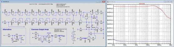
I have altered the Rbb to 120R and as you probably knew, this alters the wideband noise at behind the OPA2210 not that much compared to the ZTX transistors, from 32nV/rtHz to 42nV/rtHz up to 100Khz, quite remarkable.
The image below shows the noise directly after the OPA2210 still before the 4k76 and 47uF filter, giving a better view on things.
Red is for the bandgap solution and blue for the ADR6041.
Hans
.
You don't have to add anything on your new PCB because of me.
I was just highly interested in this Vref circuit you proposed, never saw this before and to get some feeling how it performed, I just compared it to a simple alternative.
I have altered the Rbb to 120R and as you probably knew, this alters the wideband noise at behind the OPA2210 not that much compared to the ZTX transistors, from 32nV/rtHz to 42nV/rtHz up to 100Khz, quite remarkable.
The image below shows the noise directly after the OPA2210 still before the 4k76 and 47uF filter, giving a better view on things.
Red is for the bandgap solution and blue for the ADR6041.
Hans
.
Attachments
IHMO relays probably won't affect the sound like the presence of switching transistors might ")
That said, all the opamps will have some cumulative effect as well. For instance, my AK4499 dac only has one opamp per channel, an OPA1612 for IV. Everything else is discrete. Does it matter? The last year or so of research has convinced me that it does.
That said, all the opamps will have some cumulative effect as well. For instance, my AK4499 dac only has one opamp per channel, an OPA1612 for IV. Everything else is discrete. Does it matter? The last year or so of research has convinced me that it does.
Last edited:
I might get away with forcing both data and inverse data to zero or using the output enables of the 74LV574's, although both will result in a common-mode voltage jump that has to be corrected by the first filter stage's common-mode loop. I fixed the bug I found and placed some 0 ohm resistors, so I will be able to experiment with the muting circuit, see the attachment. Everything is re-annotated, so the names may be different from before.
Attachments
OK Mark, the next version will be DAC3_4.pdf then.
I just looked up my calculations and I calculated 9.4224 nV/sqrt(Hz) at 27 degrees before amplification by four with the NST45011 base resistances. 42/4 = 10.5, so the calculation and simulation are close.
With no base resistance at all I calculate 6.2625 nV/sqrt(Hz), so that's not that close to 32/4 nV/sqrt(Hz). The differences between the squares of the simulated and calculated values are about the same in both cases, though: 21.468E-18 V^2/Hz or 24.781E-18 V^2/Hz, 9.358E-18 V^2/Hz of which is op-amp voltage noise and feedback network noise.
I have altered the Rbb to 120R and as you probably knew, this alters the wideband noise at behind the OPA2210 not that much compared to the ZTX transistors, from 32nV/rtHz to 42nV/rtHz up to 100Khz, quite remarkable.
I just looked up my calculations and I calculated 9.4224 nV/sqrt(Hz) at 27 degrees before amplification by four with the NST45011 base resistances. 42/4 = 10.5, so the calculation and simulation are close.
With no base resistance at all I calculate 6.2625 nV/sqrt(Hz), so that's not that close to 32/4 nV/sqrt(Hz). The differences between the squares of the simulated and calculated values are about the same in both cases, though: 21.468E-18 V^2/Hz or 24.781E-18 V^2/Hz, 9.358E-18 V^2/Hz of which is op-amp voltage noise and feedback network noise.
Last edited:
IHMO relays probably won't affect the sound like the presence of switching transistors might
That said, all the opamps will have some cumulative effect as well. For instance, my AK4499 dac only has one opamp per channel, an OPA1612 for IV. Everything else is discrete. Does it matter? The last year or so of research has convinced me that it does.
Maybe Jam can help you do a NRTZ DAC sans opamps, there's a challenge.
This threads DAC probably won't have near DR of 4499 but it should be free
of any noise floor modulation AFAICS.
Great thread.
TCD
I did design a return-to-zero DAC with no op-amps some time ago, see https://linearaudio.net/sites/linearaudio.net/files/03 Didden LA V13 mvdg.pdf or Valve DAC from Linear Audio volume 13 It has some noise modulation, presumably due to imperfect settling, but not to such an extent that it bothers me.
Last edited:
I did design a return-to-zero DAC with no op-amps some time ago, see https://linearaudio.net/sites/linearaudio.net/files/03 Didden LA V13 mvdg.pdf or Valve DAC from Linear Audio volume 13 It has some noise modulation, presumably due to imperfect settling, but not to such an extent that it bothers me.
Sorry Marcel, I meant to say RTZ. Not enough sleep lately. This project looks great especially the PCM -> DSD conversion.
I'm also interested to see differences in a DAC chip that plays native DSD
when fed an RTZ stream. Will the RTZ coding make up for any DAC
shortcomings.
TCD
Maybe Jam can help you...
PM sent.
Great thread.
Very interesting thread for sure.
I'm also interested to see differences in a DAC chip that plays native DSD
when fed an RTZ stream. Will the RTZ coding make up for any DAC
shortcomings.
TCD
You can try feeding 0 data 0 data 0 data... and a doubled clock into a DAC with native DSD interface, but I doubt if that will help. Normally a DSD DAC chip should have built-in return-to-zero circuits or other countermeasures against intersymbol interference. Besides, when you feed 0 data 0 data 0 data 0 data into a DSD DAC, it sees a large negative offset. When half the data bits are 1, the DAC gets a signal where on average a quarter of the bits is 1. Normally that would be the code for a maximum negative signal.
There were a couple of calculations I still needed to do, like calculating the correct value for the upper left resistor in the bandgap and calculating the dynamic current drawn by the digital parts when the input signal is a 27 Mbit/s bitstream. It turns out that those currents are a lot higher than I anticipated, so I have changed the circuit as attached. Meanwhile I'm also working on a PCB.
Attachments
You can try feeding 0 data 0 data 0 data... and a doubled clock into a DAC with native DSD interface, but I doubt if that will help. Normally a DSD DAC chip should have built-in return-to-zero circuits or other countermeasures against intersymbol interference. Besides, when you feed 0 data 0 data 0 data 0 data into a DSD DAC, it sees a large negative offset. When half the data bits are 1, the DAC gets a signal where on average a quarter of the bits is 1. Normally that would be the code for a maximum negative signal.
Got it, thanks Marcel.
So would this be the reason why there is a major difference in OP swing on DAC's that can handle both native DSD and PCM?
Cheers
Terry
I don't know. What chip do you have in mind?
Most sigma-delta DACs use multibit sigma-delta modulators nowadays and those can be driven a bit harder than single-bit modulators, such as those used for generating DSD. That could be a reason.
If it's a direct DSD recording (analogue mix or microphone feed converted straight to DSD), then the recording is likely to be soft, because you will need some headroom during recording and there is no simple way to increase the level of a DSD signal after recording.
Update: I've made a board layout, or actually two of them, as I took nautibuoy's advice and split the circuit into the RTZ logic + reference + DAC (together on a four-layer board) and the reconstruction filter (separate two-layer board). One advantage is that one can experiment with the filter while leaving the DAC as is or the other way around, another advantage that I could put the RTZ logic on one side of the DAC and the reference on the other side without ending up with long wires to the filter. See the attachments, I'll post the KiCad databases later.
Attachments
- Home
- Source & Line
- Digital Line Level
- Return-to-zero shift register FIRDAC