What is Delta-Sigma? In quantified math is the same as derivative-integral in linear math. In electronics with limited frequency is simply high pass-low pass. The most known is the recording-playback RIAA curve. As on records the high frequencies which have much smaller amplitudes than the lowers, physically the groove will contain very little information about high frequencies, besides the hiss of the stylus friction noise. If the signal is recorded with the derivative function, the high frequencies are better described and on the playback the integrator cleans the hiss of the stylus bringing back the initial spectrum.
This is to be applied on the DAC to eliminate noises created by switching spikes internal R2R noise and due to step character of the analog converted signal.
The Delta hence is the difference in level between the actual and the preceding sample. I only need to delay the signal one clock and subtract with the actual and I get the derivative function

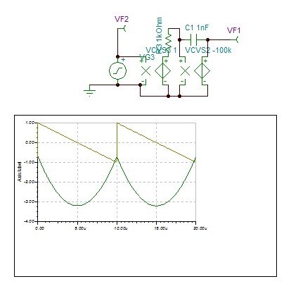
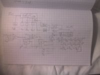
The left circuit shows this, the signal from the sampler 44khz is delayed 22us and the subtracted signal now is a cosine derivative of the input.
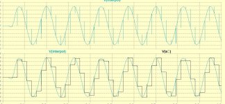
Now, if I integrate back the signal all the DAC noises will be attenuated and the step cosine will become ramped sine wave. The signal with 1khz becomes too clean sinusoidal , I increased to 8khz to be compared with the step wave. You can remark that very little filtering is necessary.
All is not bright, instead of sigma (accumulating discreet values) as I integrated it, the high frequency information in step is eliminated and the DAC has -3db response about 11khz. Band pass filter might re equalize but the lost information is not valuable, better can be done by interpolation that I explain in few.
To remark that the Delta is described with double precision than the signal occupying 17 bits.
This is to be applied on the DAC to eliminate noises created by switching spikes internal R2R noise and due to step character of the analog converted signal.
The Delta hence is the difference in level between the actual and the preceding sample. I only need to delay the signal one clock and subtract with the actual and I get the derivative function
The left circuit shows this, the signal from the sampler 44khz is delayed 22us and the subtracted signal now is a cosine derivative of the input.
Now, if I integrate back the signal all the DAC noises will be attenuated and the step cosine will become ramped sine wave. The signal with 1khz becomes too clean sinusoidal , I increased to 8khz to be compared with the step wave. You can remark that very little filtering is necessary.
All is not bright, instead of sigma (accumulating discreet values) as I integrated it, the high frequency information in step is eliminated and the DAC has -3db response about 11khz. Band pass filter might re equalize but the lost information is not valuable, better can be done by interpolation that I explain in few.
To remark that the Delta is described with double precision than the signal occupying 17 bits.
Attachments

Last edited:
Worth checking out: Valve DAC from Linear Audio volume 13 as an implementation. In the thread there’s quite a bit of information which may help you.
Last edited:
The circuits of post #1 are actually more similar to a delta modulator than to a sigma-delta (or delta-sigma) modulator.
May be I should call it delta-integral, but it is not single bit DAC.The circuits of post #1 are actually more similar to a delta modulator than to a sigma-delta (or delta-sigma) modulator.
This circuit is only to show the principle of the theory.Also have you looked at the “alternate solver” in LTSpice? Numerical precision is higher.
I am a novice in LT, I don't know why I can't get ac analysis work.
Attachments
Try here: Delta-sigma modulation - Wikipedia
That make sense?
Also of possible interest:
http://site.ieee.org/scv-sscs/files/2012/06/Oversampling-Wooley_SCV-ver2.pdf
That make sense?
Also of possible interest:
http://site.ieee.org/scv-sscs/files/2012/06/Oversampling-Wooley_SCV-ver2.pdf
Last edited:
I started my R&D engineer career in 1979 designing CVSD digital military communication in French company LMT.
This circuit has nothing to do with delta modulator. Instead of transforming the 16bit data into analog, the delta is transformed into analog and integrated. In fact the delay is made of 64bit shift register MC14517 and feeds inverted to a second DAC TDA1387 whose output current is tied with the first TDA1387 which receives the direct data. The delta is obtained at the current node to feed an integrator.
This circuit has nothing to do with delta modulator. Instead of transforming the 16bit data into analog, the delta is transformed into analog and integrated. In fact the delay is made of 64bit shift register MC14517 and feeds inverted to a second DAC TDA1387 whose output current is tied with the first TDA1387 which receives the direct data. The delta is obtained at the current node to feed an integrator.
Last edited:
The circuits of post #1 also have absolutely nothing to do with delta-sigma (or sigma-delta) modulation. They consist of a DAC followed by filters. If I understand post #9, you have actually implemented the delay digitally and used a kind of FIRDAC structure to make the first filter.
The analogy with delta modulation and with DPCM is that at the output of the first filter, you have a discrete-valued signal (with lots of possible values, but still discrete) that depends on the changes in the input signal.
The analogy with delta modulation and with DPCM is that at the output of the first filter, you have a discrete-valued signal (with lots of possible values, but still discrete) that depends on the changes in the input signal.
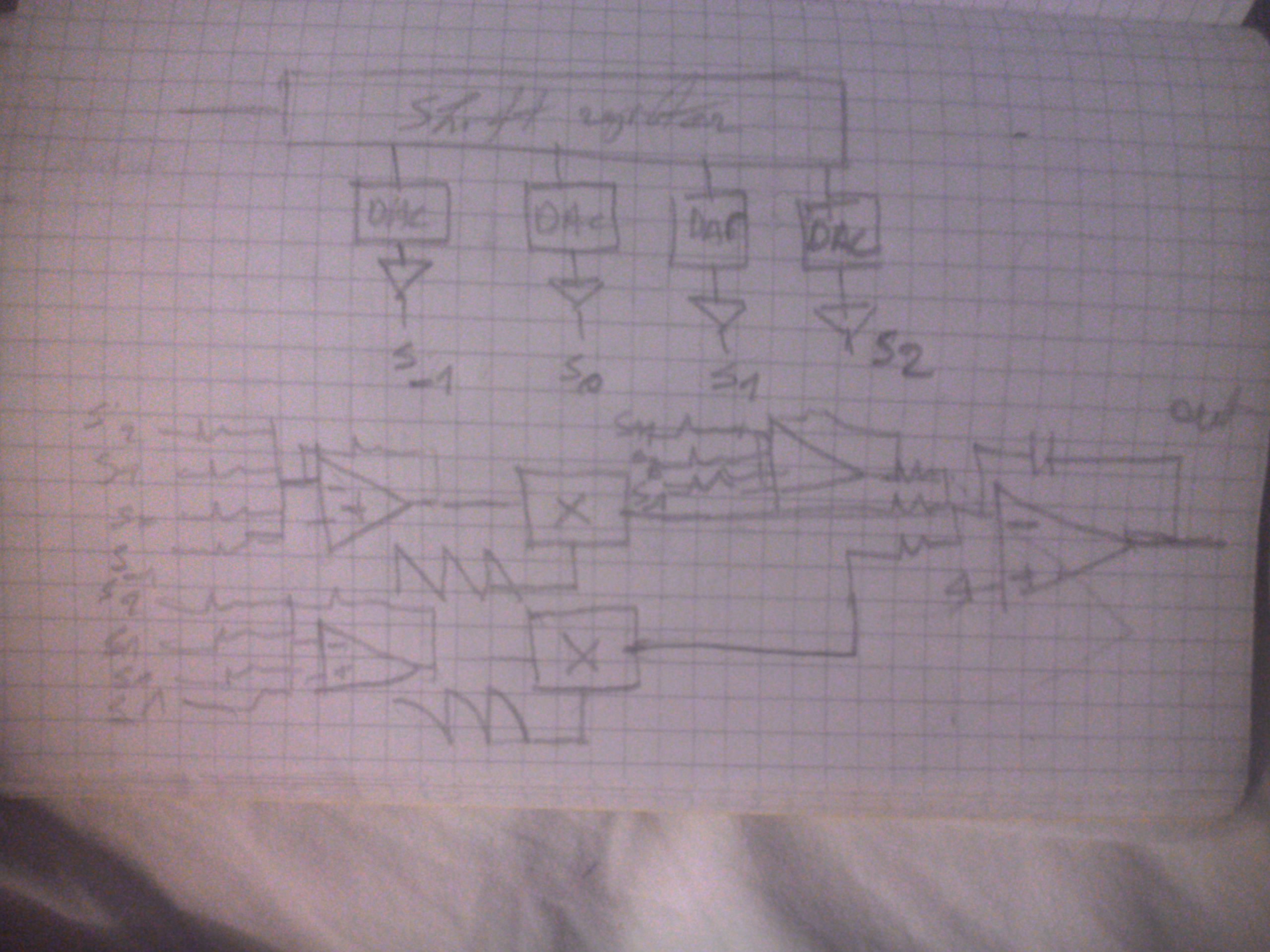
This is a sketch of two different ways with no filters.
The first, the delta is obtained digitally by subtracting the actual data from the precedent and the 17 bits delta value is transformed into analog current to be immediately integrated.
The second, the 16 bit data is transformed into analog current but it get subtracted by the current value of the precedent data, to inject into the integrator the delta information. The circuit in post 1 simulate both types.
Attachments
In both cases, you have a filter: a digital FIR filter with transfer 1 - z^-1 in the upper version and a mixed-signal FIR filter (a FIRDAC actually) with transfer 1 - z^-1 in the lower version (and of course an integrator in both cases).
By the way, I mistook the things on the left in the schematics of post #1 for digital to analogue converters, but apparently they are sample and holds.
I don't understand at all what the key message of this thread is. Do you want to apply pre-emphasis to a DAC using a FIRDAC structure and de-emphasis with an analogue integrator to suppress the higher-frequency parts of the quantization noise? What's the purpose of it all?
Last edited:
As I already explained you can see the delta sigma in electronics as high pass, low pass. Indeed, the delta or the limited derivative function you can see it as first order FIR high pass with cutoff frequency of Fck/2 that is 22khz. I look at it as the quantified derivative delta. You can also consider the integrator as first order low pass filter of few hertz cutoff, which is the case, and there you go with RIAA. As it can be seen, the integrator cleans the noises of the DAC and outputs already filtered ramped instead of stepped output.
The analog interpolator will give the straight ramps some curvature.
The analog interpolator will give the straight ramps some curvature.
Last edited:
You might be interested in Eugene B. Hogenauer, "An economical class of digital filters for decimation and interpolation", IEEE Transactions on Acoustics, Speech, and Signal Processing, volume ASSP-29, No. 2, April 1981, pages 155...162, which is the original article about CIC filters (cascaded integrator-comb filters). What you have come up with is basically a mixed-signal CIC interpolation filter with infinite interpolation.
Interpolation
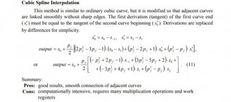
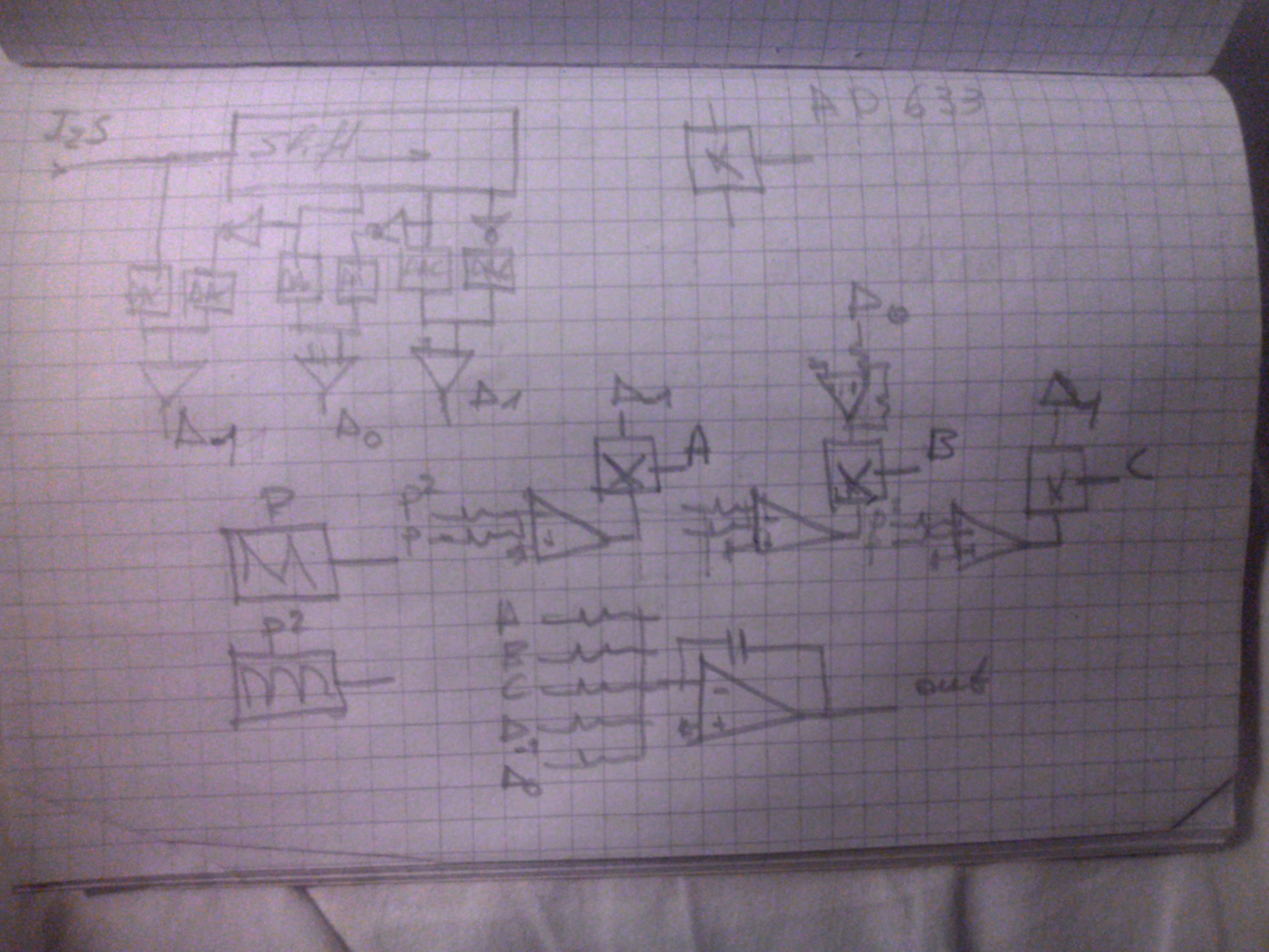
To interpolate linearly and smoothly the sampled points I will temp the spline cubic interpolation. This is the formula that my analog computer will accomplish.
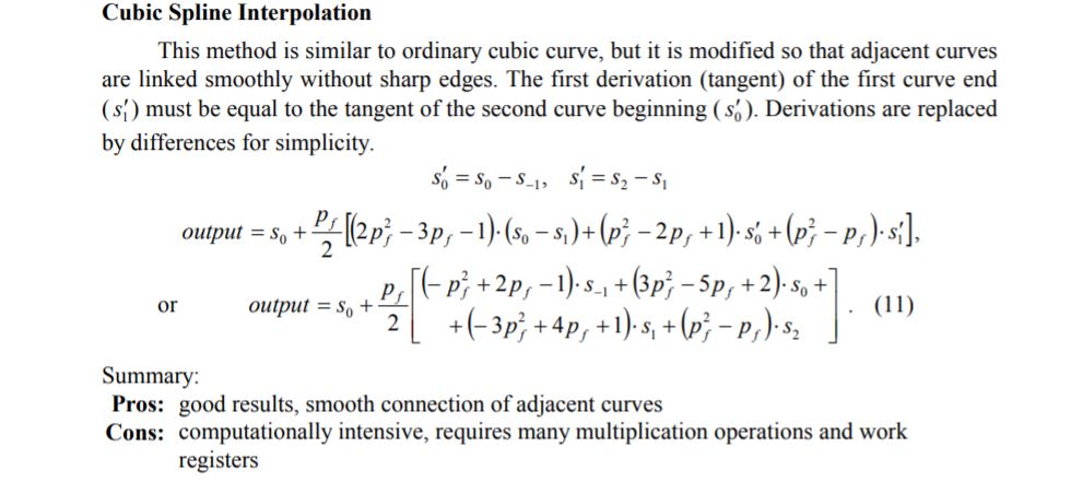
This needs 4 samples to be fed a future s-₁, a present s₀, and two precedents s₁, s₂.
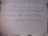
The formula 11 is to be grouped in terms of P³,P²,P, and than derivate it yields (k1s-₁+k2s₀ +k3s₁+k4s₂)P² + (m1s-₁..............m4s₂)P + (n1s-₁ +n2s₀+n3s₁)
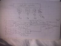
This operation is accomplished by the following circuit.
The P² and the P functions are realized by square law and linear saw tooth waves multiplied by the mixed values of of the samples. an example of P is the following
As shown the saw tooth provokes on the integrator output parabolic waves whose amplitude and the polarity (bump or hump) is determined by the 4 samples.
To interpolate linearly and smoothly the sampled points I will temp the spline cubic interpolation. This is the formula that my analog computer will accomplish.
This needs 4 samples to be fed a future s-₁, a present s₀, and two precedents s₁, s₂.
The formula 11 is to be grouped in terms of P³,P²,P, and than derivate it yields (k1s-₁+k2s₀ +k3s₁+k4s₂)P² + (m1s-₁..............m4s₂)P + (n1s-₁ +n2s₀+n3s₁)
This operation is accomplished by the following circuit.
The P² and the P functions are realized by square law and linear saw tooth waves multiplied by the mixed values of of the samples. an example of P is the following
As shown the saw tooth provokes on the integrator output parabolic waves whose amplitude and the polarity (bump or hump) is determined by the 4 samples.
Attachments
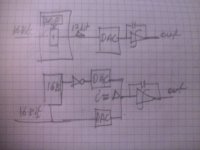
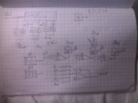
This is a second method using deltas instead of samples by the first equation

If I rearrange the derivative of the equation as shown bellow, I can make the following circuit.
Although it has two more DACs and one extra multiplier, the adjustment is much easier.
If I rearrange the derivative of the equation as shown bellow, I can make the following circuit.
Although it has two more DACs and one extra multiplier, the adjustment is much easier.
Attachments
I changed the configuration to suit better to my humble understanding.
I bring back my initial delta- sigma DAC which gives excellent result up to 8khz, on this I add an additive to enhance the high frequencies by adding interpolated compliment to the linear interpolated ramps.
The circuit I will try to simulate will have the following topology.
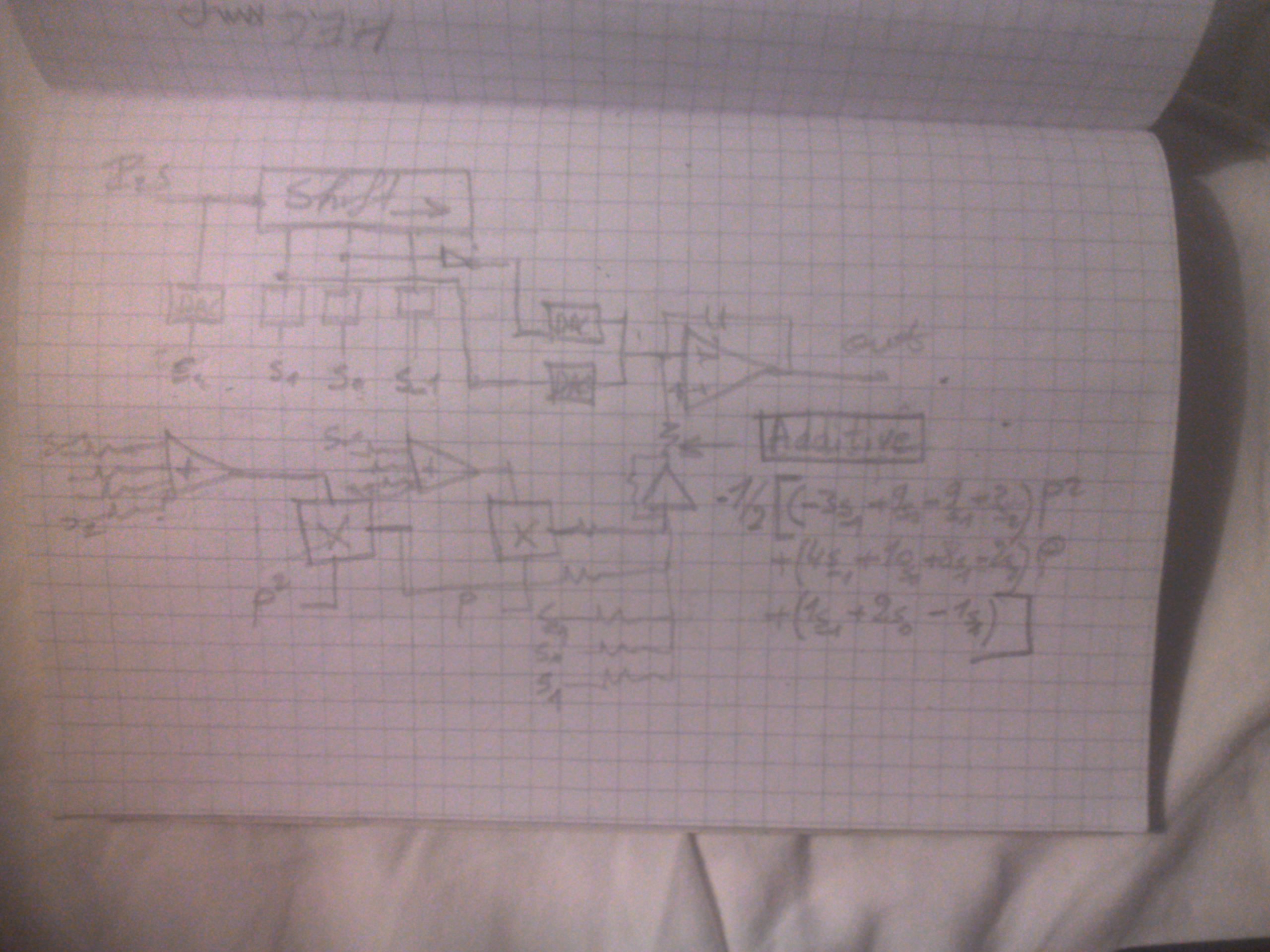
The equation 11 is erroneous, but if the s₀ of the beginning is erased it gives exactly the additive function after the integrator, the derivative of it I add before integrator.
I bring back my initial delta- sigma DAC which gives excellent result up to 8khz, on this I add an additive to enhance the high frequencies by adding interpolated compliment to the linear interpolated ramps.
The circuit I will try to simulate will have the following topology.
The equation 11 is erroneous, but if the s₀ of the beginning is erased it gives exactly the additive function after the integrator, the derivative of it I add before integrator.
Attachments
Last edited:
I surely don't follow everything here but have a question. What property in a finished DAC ar you trying to optimise on? Or is it just an "other way" of doing it that is of interest?
//
//
For now it is not easy to understand what is going on here as everything is theory and feasibility. I am using analog sampled signal representing as digital source which makes things more confusing.
The first post gives the initial idea how to reduce noises generated by the DAC and output a linear interpolated signal. Now I am trying out sophisticated interpolation technique in analog mode, that is not practical digitally, to avoid filtering. This is more mathematics than electronics for now.
The first post gives the initial idea how to reduce noises generated by the DAC and output a linear interpolated signal. Now I am trying out sophisticated interpolation technique in analog mode, that is not practical digitally, to avoid filtering. This is more mathematics than electronics for now.
- Home
- Source & Line
- Digital Line Level
- Analog Delta-Sigma interpolation DAC