Hi,
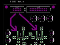
I would need advice how to lead I2S bus for 2 x DAC converter in monoaural connection. I2S input bus is isolated from xmos or fi-fo. I want the best possible quality and I'm not sure if it's better to use a parallel connection for both DACs without a driver or use driver for each DAC separately. I'm afraid about my driver, that it would degrade the I2S bus. If you recommend me a driver as a better solution, can you write me what type I should use to avoid degradation? The distance of the input connectors from the DAC is very small. I don't have enough space, so ideal SSOP package. DVDD voltage is 5V, the driver must be able to perfectly process the incoming 3.3V logic state. Or 3,3V and I will have to use another stabilizer for this driver because I don't have a 3.3V voltage on this board.
Can I use one driver for both DACs and output resistors for DAC-A and DAC-B or better for each DAC driver IC separately?
Attachments
A fanout of x2 isn't a problem for CMOS chips. You could check the input capacitance for
the DACs in question and estimate the rise-time from that and the drive strength of the driver chip. Factor in the pcb trace capacitance too.
If the traces are short I don't see a problem. Any small increase in rise and fall times will be the same for all signals to a first approximation anyway.
the DACs in question and estimate the rise-time from that and the drive strength of the driver chip. Factor in the pcb trace capacitance too.
If the traces are short I don't see a problem. Any small increase in rise and fall times will be the same for all signals to a first approximation anyway.
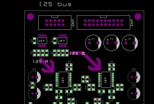
It looks very good with placement and connection in my layout. The signal will be isolated, I want to buy some usb to i2s converter, I haven't studied which yet. I will buy it as soon as I send the PCB to the production process. Several members here sell xmos where i2s is already isolated.
May I ask which specific circuit you used? I am also thinking about the possibility to use something from the production of tiny logic, like the NC7SZ125 and SOT23 package.
Thank you for your help
May I ask which specific circuit you used? I am also thinking about the possibility to use something from the production of tiny logic, like the NC7SZ125 and SOT23 package.
Thank you for your help
Attachments
I used 74AUP1G79 from Nexperia, a single flip-flop in a chip, so there were necessary 3 pcs. for every channel.
For my next project I want to use MC100LVEL30 from Onsemi, 3 flip-flops in a chip, as a re-aligner chip for a FPGA based reclocker. This will be an USB asynchronous (XMOS), synchronous* FIFO reclocker. I have start learning FPGAs, and as much as I read about, as much I love them.
*synchronous means here that there will only be a small amount of RAM for FIFO buffer, but FPGA will tell to XMOS to slow down if the buffer tends to be full, and vice-versa if the buffer is going to be empty, so some sort of synchronicity between FPGA and XMOS.
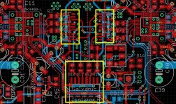
I have another dilemma. My voltage DVDD is 5V. I can use SN74AUP1G79 but I will have to add a stabilizer. I can also use SN74LVC1G79 and 5V DVDD, which is slower. AUP family is 260MHz, LVC family is 150Mhz. Input I2S bus will be only 3.3V.
Therefore, I prefer to use one stabilizer from 5V to 3.3V and use faster SN74AUP1G79. Is this idea correct?
For MCLK I would use TINYLOGIC NC7SZ125.
Therefore, I prefer to use one stabilizer from 5V to 3.3V and use faster SN74AUP1G79. Is this idea correct?
For MCLK I would use TINYLOGIC NC7SZ125.
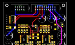
Can you please check it? Do you recommend me keep the MCLK buffer or should I remove it and connect the MCLK without the buffer directly from pin input connector?
Thank you for help.
Thank you for help.
Attachments
Last edited:
I'm planning to buy an XMOS USB receiver, before I came across the Cyber drive AURA USB DAC, which uses XMOS inside it with CS4398. It's as cheap as (if not cheaper) than an XMOS-I2S converter.
Looking at the pinout, it seems like the DAC accepts I2S input for PCM and the pins are accessible by hand soldering. Is it possible to solder wires to tap into the I2S DAC input pins of the CS4398?
Looking at the pinout, it seems like the DAC accepts I2S input for PCM and the pins are accessible by hand soldering. Is it possible to solder wires to tap into the I2S DAC input pins of the CS4398?
- Home
- Source & Line
- Digital Line Level
- I2S connection for 2 x DACs