If you look at the diagram on the first page of CS4272 datasheet, Serial Audio Input points in the direction of going into the dac chip, and Serial Audio Output points in the direction leaving the dac chip (which would be for the AD since it would send data to the USB board, only the dac is for receiving input data).
My interpretation of that would be that you probably do have the data lines cross connected.
My interpretation of that would be that you probably do have the data lines cross connected.
Last edited:
With "stand alone" pin-out in mind, I pulled I2S/LJ pin#13 to VL (3,3V) with a 10k resistor and attached M1, M0 pins#11,12 to ground for starters. But I messed the data lines... I had to go out for a while. I'm going to fix that now.
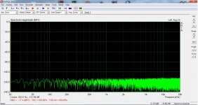
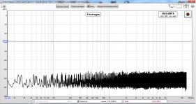
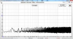
So, I've been playing with this. With ARTA, it needs to configure M0, M1 accordingly to each sampling rate or it won't work. Then it will do what's shown in the previous post. With REW -java drivers- it's a different story. With M0,M1 both set to 1 it will do all sampling rates from 44.1 to 96kHz. I also keeps the noise floor down where I would expect to see it from a 24bit chip. Leaving M0,M1 fixed is very handy but is it the correct thing to do? What would be your choice?
Attachments
Most USB boards have some output signals referred to as F0 through F3. Some people code them a little different (there should be a table somewhere saying what mean), but they contain the info you need to automatically set M0,M1. Just figure out the mapping needed, and implement it.
I suppose the microcontroller should have this output but I can't see any pins on the board providing it. There is S/PDIF output and volume control pins. Also there is a connector for an OLED screen (a second I2C and power supply). This screen shows VU meter and sampling rate. But I don't even dare to sniff around this...
The information about sample rates is apparently in that data stream. Probably easy enough to get it out. Cost about $10 to find out: Amazon.com: HiLetgo USB Logic Analyzer Device With EMI Ferrite Ring USB Cable 24MHz 8CH 24MHz 8 Channel UART IIC SPI Debug: Clothing ...or same thing available from ebay or aliexpress. Not exactly what it claims to be, but good enough to decode I2C.
EDIT: It could also be some other pins on the board provide undocumented sample rate information. Only way to find out would be to measure the voltage on, say, DIO1 through DIO4 and see if the follow the same rate in some pattern. 4-bits is enough to encode clock family (44/48) and oversampling multiplier.
Either poke around looking around for what you need, or if this is for stereo only, just get a better USB board.
Last edited:
Thanks! I'll think about it. Honestly, this is the least problem for me now. I could go on with a four position switch. A question arise: when SCL, SDA become M0,M1 are they still sensitive to long wires?
SCL, SDA cannot exactly 'become' M0, M1. The information from I2C bus would have to be extracted and exported as logic signals to drive M0, M1. Easy for an Arduino to do, or something like that.
The Diyinhk board has very little functionality in terms of control. It can reset the ADC and the DAC and it can control the volume. Anything else has to be programmed into the XMOS. It has a separate I2C port just for controlling audio devices.
One would not drive M0 and M1 as they are standalone mode configuration pins and are tied high or low permanently that is why there is only timing information for when they are configured as I2C or SPI pins
Seems to me if the OP wants a relatively easy solution it would be to put the device into standalone mode.
Since I'm totally unable for any customized solution in the software domain, the manual control is all I could ask for. I'm keeping it this way for now. It could be changed at any time if something better come up. At the time being, I have only found the DIYINHK and a MiniDSP boards that can do usb to I2S in and out.
I need to thank you all for putting me on the right track with this. Now I have to rebuild the prototype properly. If everything is OK, I'll post it in the relevant section of the forum. I'll keep you updated.
I need to thank you all for putting me on the right track with this. Now I have to rebuild the prototype properly. If everything is OK, I'll post it in the relevant section of the forum. I'll keep you updated.
Um, If you are interpreting what diyinhk says about the capabilities of your USB board, looks like they sell an optional Thesycon Windows driver that supports multichannel playback and Native DSD. Its unclear to me if that driver supports I2S input or not from what I can see on the driver page. Maybe only the firmware has full-featured support, but not the Windows driver? Might work with full features in Linux or something. Please let us know what you find out.
Last edited:
What I mean is data for dac and adc i.e. recording and playback, which I already achieved although I have to tidy up my set up for critical evaluation.
Edit: I'm using the two channel drivers as provided free from DIYINHK.
Edit: I'm using the two channel drivers as provided free from DIYINHK.
Last edited:
Thanks! I'll think about it. Honestly, this is the least problem for me now. I could go on with a four position switch. A question arise: when SCL, SDA become M0,M1 are they still sensitive to long wires?
Manual switches for M0 & M1 should work. Long wires are OK. I2C can be sensitive to propagation delay and interference, hence the wire length advisory. I suggest you include a push button switch to assert /RST when the need arises.
- Home
- Source & Line
- Digital Line Level
- CS4272 stuck in power down mode