I am refreshing an ADCOM GDA-600 DAC as a learning experience and trying to understand some of the LPF used here.
This DAC uses dual channel op-amps per channel. To my understanding, each opamp does both I/V and filtering.
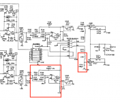
I've attached the relevant section of the schematic.
A few questions:
1) Is it correct that this is a "second order LPF" ?
2) There is an LC filter on the output. Is this actually needed given that we already have active filtering?
3) Can the circuit be optimized here? The cap values here seem to be non-standard based on Digikey and Mouser inventory. I've also read somewhere that the resistor value should be between 10K-100K while 1.21K is used here.
Thanks!
P.S I will be replacing the stock op-amps with OPA2132 if that matters
This DAC uses dual channel op-amps per channel. To my understanding, each opamp does both I/V and filtering.
I've attached the relevant section of the schematic.
A few questions:
1) Is it correct that this is a "second order LPF" ?
2) There is an LC filter on the output. Is this actually needed given that we already have active filtering?
3) Can the circuit be optimized here? The cap values here seem to be non-standard based on Digikey and Mouser inventory. I've also read somewhere that the resistor value should be between 10K-100K while 1.21K is used here.
Thanks!
P.S I will be replacing the stock op-amps with OPA2132 if that matters
Attachments
A few questions:
1) Is it correct that this is a "second order LPF" ?
Looks a lot like a 3rd order Sallen-Key LPF.
2) There is an LC filter on the output. Is this actually needed given that we already have active filtering?
Dacs can produce an lot of RF on the analog outputs. Hopefully, the opamps where chosen because they could handle the RF without distorting. No guarantee any downstream equipment will be designed to tolerate that, so better to filter it out as much as possible.
3) Can the circuit be optimized here? The cap values here seem to be non-standard based on Digikey and Mouser inventory. I've also read somewhere that the resistor value should be between 10K-100K while 1.21K is used here.
The cap values are probably calculated to give the correct filter poles locations. You can try recalculating with optimization favoring more common cap values, but the resistor values may be odd.
On the one hand, resistors make noise and higher value resistors make more noise than low value resistors do. On the other hand, opamps will distort if they can't drive too low an impedance load. Opamps typically used for state of art dacs can tolerate low-ish impedances (~600 ohms), and using low-ish value resistors can help improve noise performance.
P.S I will be replacing the stock op-amps with OPA2132 if that matters
Why? If you think new opamps are needed, you might consider OPA1612 which are used with state of art dac chips like AK4499 and the slightly older ES9038PRO. They may be more tolerant of RF that the lower bandwidth OPA2132. In part it depends on what dac is ahead of the opamps in the schematic you show. Older dacs with more clock noise on the analog outputs may benefit from using faster, somewhat less linear opamps. For an old 16-bit dac, the trade off to a faster, less linear opamp may be worthwhile. Point is, it depends.
On the beginning there is an active I/V converter. It has some first order LP filter as usual, followed by a passive RC filter. Then in a red box there is a second order active filter, probably Butterworth. Not sure, as there are variations having the same layout, but it was popular. Look at some examples, you can calculate your cut-off frequency before other guys come in:
Second-order Butterworth low-pass filter circuit. | Download Scientific Diagram
Calculating the cut off frequency of a filter circuit if you know all the component values - Electrical Engineering Stack Exchange
As a rule, if you don't have a good RLC meter, you should not touch values of the active filter.
LC filter on the output has multiple functions. It prevents by example a radio frequency entering back to your active filter opamp.
I don't know what resistors you want to modify, lets others talk.
Thanks alot for your comments, I will take some time to read carefully and digest.
Somee quick follow ups:
Shouldn't the active filter take care of this? Unless the cut-off frequencey is higher than the passive one?
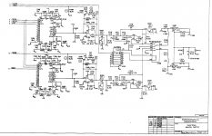
The DAC is based on PCM63P-J. Full schematic of this portion is attached.
The op-amp in there right now is badged Adcom 7AA and most people that swapped these out (seems like most people used dual OPA627 with adapters) report improved sonics (subjectively).
The cost of a modern op-amp is not high and if improvements could be had I'd like to explore them.
Somee quick follow ups:
Dacs can produce an lot of RF on the analog outputs. Hopefully, the opamps where chosen because they could handle the RF without distorting. No guarantee any downstream equipment will be designed to tolerate that, so better to filter it out as much as possible.
.
Shouldn't the active filter take care of this? Unless the cut-off frequencey is higher than the passive one?
Why? If you think new opamps are needed, you might consider OPA1612 which are used with state of art dac chips like AK4499 and the slightly older ES9038PRO. They may be more tolerant of RF that the lower bandwidth OPA2132. In part it depends on what dac is ahead of the opamps in the schematic you show. Older dacs with more clock noise on the analog outputs may benefit from using faster, somewhat less linear opamps. For an old 16-bit dac, the trade off to a faster, less linear opamp may be worthwhile. Point is, it depends.
The DAC is based on PCM63P-J. Full schematic of this portion is attached.
The op-amp in there right now is badged Adcom 7AA and most people that swapped these out (seems like most people used dual OPA627 with adapters) report improved sonics (subjectively).
The cost of a modern op-amp is not high and if improvements could be had I'd like to explore them.
Attachments
Shouldn't the active filter take care of this? Unless the cut-off frequencey is higher than the passive one?
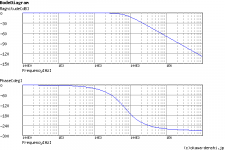
If you run a frequency response simulation of a Sallen-Key LPF you may well find that while its rejection is good up to a few hundred kHz, its output starts to rise again after a while with increasing frequency. The LC filter in your schematic doesn't show a value for the inductor so its turnover frequency can't be established but its likely above 1MHz where the SK active filter runs out of steam.
I am refreshing an ADCOM GDA-600 DAC as a learning experience and trying to understand some of the LPF used here.
This DAC uses dual channel op-amps per channel. To my understanding, each opamp does both I/V and filtering.
I've attached the relevant section of the schematic.
A few questions:
1) Is it correct that this is a "second order LPF" ?
Your DAC has a fourth order, active LPF in the 2 opamp section prior to the
OP LC filter (which is most likely at a much higher freq).
The first oder is wrapped around the the first I-V opamp. The second opamp, as Mark said, is a SK 3rd order LPF.
The FET switch on first OPA is likely a de-emphasis filter enable.
2) There is an LC filter on the output. Is this actually needed given that we already have active filtering?
Probably not. It's difficult to say. It may have been needed for compliance. I've worked on some pretty poorly implemented DACs that had huge amounts of RF noise, not from the DAC itself but just bad design.
Do you have a CRO? This will enable you to see any RF noise on the OP and many other things.
3) Can the circuit be optimized here? The cap values here seem to be non-standard based on Digikey and Mouser inventory. I've also read somewhere that the resistor value should be between 10K-100K while 1.21K is used here.
The PCM63 was one of the best multibit sign magnitude DACs ever made, they can sound superb with the right implementation.
Being a sign mag DAC, they don't put out a lot of RF or glitching noise so LPF requirements are much less than modern DS DAC's.
I ran a PCM63 DAC with first order LPF at around 50 to 70kHz (from memory) no problems. Ideally a higher order linear phase filter is better but
it was a case of added complexity (2 opamps / 3rd order LPF) versus simple
1 opamp. It's an easy mod and you can decide.
There are many tweaks that can be done to the PCM63 but it depends on your experience, test gear, constraints of existing design and how much work
you want to put into it.
Start with the opamps, components, PS caps. You can also disconnect BPO
from DAC OP and use a CCS instead. Carefully study the PCM63 data sheet
so you know what you are dealing with.
TCD
The PCM63 was one of the best multibit sign magnitude DACs ever made, they can sound superb with the right implementation.
Being a sign mag DAC, they don't put out a lot of RF or glitching noise so LPF requirements are much less than modern DS DAC's.
Lynn Olson's experience with PCM1704 (a later design than PCM63 but with similar architecture) was rather different : dsd olson
Seeing as its a very long piece I'll snip out the relevant part here (underlining my own) :
The Old School alternative to delta-sigma hybrids are the pure ladder converters, the last examples being the ten-year-old Burr-Brown PCM-63 (true 20 bits at 384kHz) and eight-year-old Burr-Brown PCM-1704 (also 20 bits at 384kHz). Being true ladder converters, they require phenomenally accurate laser-trimming, ultra-performance reference voltage supplies, and pretty sophisticated engineering in the (outboard) I/V conversion. This was the converter where my Tek friend and I measured a flat comb spectrum going from 20kHz to 20MHz, then declining into the noise around 50MHz. A sobering sight to see, I can tell you. It gave me a very healthy respect for the severe demands placed on the audio section, at least the parts responsible for buffering and low-pass filtering.
Last edited:
Your DAC has a fourth order, active LPF in the 2 opamp section prior to the
OP LC filter (which is most likely at a much higher freq).
The first oder is wrapped around the the first I-V opamp. The second opamp, as Mark said, is a SK 3rd order LPF.
The FET switch on first OPA is likely a de-emphasis filter enable.
Would the first order be the C553, 220pF?
I've read elsewhere that indeed C561 (0.022uF) is a de-emphasis filter that was actually rarely used in CD production?
Probably not. It's difficult to say. It may have been needed for compliance. I've worked on some pretty poorly implemented DACs that had huge amounts of RF noise, not from the DAC itself but just bad design.
Do you have a CRO? This will enable you to see any RF noise on the OP and many other things.
Some modders removed the inductors in favor of jumpers and claim improved sonics. This could be true, but rather than follow blindly I'd like to know the reason why this would be.
Initially, I was under the impression that the Op-amp LPF could be sufficient but I'm learning here why that may not necessarily be case.
I've got a Tektronix 2235A 100 MHz scope, but I would need some guidance on how to use it for this. I've only used it to trace 1khz sine waves when I repaired a vintage Sansui AU-9500 amplifier.
There are many tweaks that can be done to the PCM63 but it depends on your experience, test gear, constraints of existing design and how much work
you want to put into it.
Start with the opamps, components, PS caps. You can also disconnect BPO
from DAC OP and use a CCS instead. Carefully study the PCM63 data sheet
so you know what you are dealing with.
Thanks for the tips. I've built quite a few amps and repaired some vintage receivers so feel like I have sufficient experience to tackle this.
For test gear I've got a Fluke 87V DMM, the Tektronix, a signal generator and Pete Millett soundcard interface that I use with ARTA to measure THD.
As this is now a 27 year old DAC, I'll be starting by replacing all electrolyics in the power supply.
Likely Pansonic FC for filter caps. I looked at the LM7805 and LM337 and increase of some of the caps there can improve ripple rejection and I will follow the recommendation.
As mentioned I want to replace the op-amp. I'll insert a socket and will start initially by trying an OPA2132AP.
The LPF caps look to be mylar (yellow axial types) and these are ones that I wanted to replace as well, and that is part of the motivation for this thread as I can't find replacements in the original values. (Sonicaps are available actually, but nothing from Mouser/Digikey)
The remaining electrolytics are around the PCM63 chip for power supply bypass. I've read the datasheet quite a bit but there are only vague recommendations there so that is why I started
PCM63P decoupling capacitors
I have a follow up to your recommendation there so will ask in that thread to keep both on topic.
Attachments
Your 3rd-order Sallen-Key filters are using 2% and 2.5% capacitors -- not easy to source and rather expensive in small quantities. The 2700, 3900, and 680pF values themselves at not unusual.
As to the 1K21 resistors, it is likely a best compromise selected specifically for that op-amp -- reducing input noise, while keeping the loading on the previous stage to an acceptable level. The notion that it *should be* between 10K and 100K might be reasonable for some certain (different) circuit/op-amp combination, but as a general rule simply does not apply.
The resistors also determine (along with the capacitors, of course) the filter's cutoff frequency; the ratio of capacitors sets the damping factor. Likely none of these variables were chosen haphazardly. In fact, the design probably underwent several iterations with simulations, test-builds, and extensive listening tests. More modern, better-sounding dual op-amps might be available today, and may even be cost-effective to try -- though not all will behave in this circuit.
Much fun and useful learning awaits your experiments. But please study the hard-earned, sage advice given earlier in the thread. Then by all means, mod to your heart's content -- keeping in the back of mind that while fun, interesting, and instructive, the result is in all likelihood less *correct* mathematically.
Regards
edit: Now that it took me a long time to compose this, I'd better go back and read your 05:27 post ..
Last edited:
Am still puzzled why you want to fiddle the mylar LPF caps.
If phase is correct about your original op-amps being rebadged LT1057s, the change to OPA2132 may bring little joy: The 1057s are 4 - 6 dB quieter and more accurate, if you believe the PDF specs.
If you pick out something different to try, make sure the mfg doesn't recommend 'no-socket' mounting. Lots of high performance models hate sockets.
Cheers
Thanks for your thoughtful and informative reply.
I may not end up replacing these. Since these caps are in the signal path I'm sure part quality can have an impact. If there are modern Polypropylene caps with same values (and tolerance), I think its worth a try.
That's an interesting point. I have no idea if the Adcom 7AA is indeed LT1057 or not. There are many testimonials that replacing it to the OPA627 made a huge difference. These are all subjective so have to take them with a grain of salt but something I would want to try for myself.
Granted the OPA2132 is not the OPA627 but I dont have direct experience with either, and I'm not willing to pay ~$100 for quad OPA627's.
I chose OPA2132 after reading through a few threads here. They seem to be a good compromise between performance, compatibility to the original circuit and cost. The original PCM63 datasheet shows a OPA2604 for I/V & filtering and the OPA2132 looks to have lower noise and lower distortion.
edit: I also compared the OPA2132P datasheets with the LT1057. The OPA2132P has lower noise and better CMRR. The LT1057 doesn't publish THD spec so I have to assume the OPA2132P is superior here as well.
Am still puzzled why you want to fiddle the mylar LPF caps.
I may not end up replacing these. Since these caps are in the signal path I'm sure part quality can have an impact. If there are modern Polypropylene caps with same values (and tolerance), I think its worth a try.
If phase is correct about your original op-amps being rebadged LT1057s, the change to OPA2132 may bring little joy: The 1057s are 4 - 6 dB quieter and more accurate, if you believe the PDF specs.
If you pick out something different to try, make sure the mfg doesn't recommend 'no-socket' mounting. Lots of high performance models hate sockets.
That's an interesting point. I have no idea if the Adcom 7AA is indeed LT1057 or not. There are many testimonials that replacing it to the OPA627 made a huge difference. These are all subjective so have to take them with a grain of salt but something I would want to try for myself.
Granted the OPA2132 is not the OPA627 but I dont have direct experience with either, and I'm not willing to pay ~$100 for quad OPA627's.
I chose OPA2132 after reading through a few threads here. They seem to be a good compromise between performance, compatibility to the original circuit and cost. The original PCM63 datasheet shows a OPA2604 for I/V & filtering and the OPA2132 looks to have lower noise and lower distortion.
edit: I also compared the OPA2132P datasheets with the LT1057. The OPA2132P has lower noise and better CMRR. The LT1057 doesn't publish THD spec so I have to assume the OPA2132P is superior here as well.
Last edited:
Am still puzzled why you want to fiddle the mylar LPF caps. If phase is correct about your original op-amps being rebadged LT1057s,
ADCOM 7AA ICs are rebadged AD712. They can be replaced with OP275, OPA2134, OPA2604, etc.
- Home
- Source & Line
- Digital Line Level
- Understanding Op-Amp LPF in DAC