You can also use lt1128, which is basically a lt1028 but is stable with gain of +1
In breadboard testing of the LT1028 for use as an I/V converter a minimal feedback capacitor of around 30pF was required for stability. For values greater than 100pF (as often around 1000pF in audio I/V converters) instability shouldn't be an issue, particularly if the capacitor is soldered across the pins of the LT1028.
I am using between 470 pf to 1000pf.In breadboard testing of the LT1028 for use as an I/V converter a minimal feedback capacitor of around 30pF was required for stability. For values greater than 100pF (as often around 1000pF in audio I/V converters) instability shouldn't be an issue, particularly if the capacitor is soldered across the pins of the LT1028.
Also tested 47pf on the feedback loop.
Only used a small 27pf compensation cap on the ne5534 but overall i like more lt1028 sound.
But i also have the feedback resistor and cap a little away from pins, about 1,5 cm maybe i should solder them direct to op amps pins.
regarding the relation between the cap and resistor values can someone explain me??
i understand the value of the resistor to convert from mili amps to volts but i don´t understand the capacitor value in relation to the value of the feedback resistor.
In other words, i want to lower the value of the resistor for example to 1k, what value of parallel cap should i use??
for example now i have 3k and 1000pf but is to much gain for my amp. I have to lower the resistor.
also i don´t know if is better to reduce the gain on the dac side or on the amp side...
Last edited:
Don't need to solder to the pins, just have the cap right next to them - many opamps are pinned out such that the output and inverting input are neighbouring pins for this reason.
The capacitor is for stability only, it only needs to be large enough to prevent oscillation, and depends on the specific opamp and the noise-gain of the circuit
I think.
However if you want low-pass filtering as well, you calculate the components values as for any other active filter. The direct feedback capacitor is still likely to be needed unless its an integrator stage (which has no resistance in the feedback path, just capacitance)
In further testing of my "LT1028" purchased from a Chinese source, I discovered that it was equal to my better "AD797" and my "NE5534", all coming from China. It should be noted that the Chinese NE5534 was true to the data sheets.
In the testing, using input signals as per the above, a 150pF feedback capacitor was insufficient for the output buffer to bypass enough transient current, resulting in serious overload on the input with long term recovery before normal function. Using a 820pF capacitor this was prevented.
Agreed. In breadboarding I normally try to use the hole next to the device to locate capacitors having high frequency implications. Using higher frequency CFA's with fast input signals you can observe the waveform shape changing when using holes farther from the line of holes extending from the chip.Don't need to solder to the pins, just have the cap right next to them - many opamps are pinned out such that the output and inverting input are neighbouring pins for this reason.
In transient testing of the "NE5534" using +/- 2ma, 25nSec square wave, a feedback capacitor is vital during the "pre-function" period (before feedback loop control) to prevent serious transient overload and recovery delays. During pre-function the output buffer behaves as a common-base device (the voltage input of the buffer can be considered fixed), whereupon currents imposed on the output terminal are directed into the power supplies. With a capacitor in the feedback path the input current transients feed through the capacitor into the common base device at the output, forming a current bypass that decreases the potential of inverting terminal overloaded.The capacitor is for stability only, it only needs to be larger enough to prevent oscillation, and depends on the specific opamp and the noise-gain of the circuit
I think.
In the testing, using input signals as per the above, a 150pF feedback capacitor was insufficient for the output buffer to bypass enough transient current, resulting in serious overload on the input with long term recovery before normal function. Using a 820pF capacitor this was prevented.
Now i reduced the feedback resistor to 680ohms, reduced the ouput gain.
In this case of vintage dacs like pcm1702 etc when reducing the feedback iv resistor gives better perfomance specs for the dac output or no??
Is better to have a smaller resistor?
On some threads off passive iv conversion some people say less is better...
In this case of vintage dacs like pcm1702 etc when reducing the feedback iv resistor gives better perfomance specs for the dac output or no??
Is better to have a smaller resistor?
On some threads off passive iv conversion some people say less is better...
Now i reduced the feedback resistor to 680ohms, reduced the ouput gain.
There are a host of competing technical factors of unknown variant contribution in a particular system. Sonics can be influenced for "better or worse", notwithstanding how these are defined, or the preferences of a listener to ultimately choose or "voice" their system to their liking.
As a couple of examples to your point, if your subsequent electronics has a high noise level the reduction in signal can detrimentally affect the signal to noise ratio of your whole system. Lower resistance can affect sonics related to interconnect cabling, including dielectric affects.
An interesting question is "what sonic affects did you find in reducing the feedback resistor to 680 Ohms?"
For now is difficult to have a true answer. First i had 2700k+470pf, now i have 680+47pf. In sonic terms i feel almost the same sound... i think.
in a technical way since i don´t have pre amp and i´m using the computer digital volume, i think i have more bits now playing. correct?? this should improve the perception of sound.
Each adjacent bit is a 1/2 or 2x change in amplitude. Since the resistance ratio is 680/2700 = 0.25, this represents a 2 bit (1/2 x 1/2) change, meaning that you need 2 more bits in the DAC for the same output. However, you are using a 20bit DAC, hence there may be no appreciable sonic difference.
As far as the capacitance goes, this is up in the air. With 2700+470pF the 3dB rolloff point is at 125KHz. With 680+47pF the 3dB point is 5MHz, as dependent upon your LT1028. It seems you are not using any reconstruction filtering afterward. Can your power amplifier deal with such signals?
Hi, please don't mind I attached my question here also.
I have little electronic background.
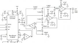
The image below is the reference output stage in PCM63 datasheet.
I would like to replace the non-inverting input I/V op amp to an inverting input I/V op amp (ADA4627).
I know inside PCM63, between pin 9 and pin 10, there is an internal 1.5K Ohm I/V feedback resistor.
I would like to ask, if I use inverting input I/V op amp...
a) Can I still use this internal 1.5K Ohm I/V feedback resistor?
b) Should I ignore pin 9 and pin 10 entirely and use an external, different value I/V feedback resistor? What value?
c) Should I add an parallel feedback capacitor? What value?
Thanks.")
I have little electronic background.
The image below is the reference output stage in PCM63 datasheet.
I would like to replace the non-inverting input I/V op amp to an inverting input I/V op amp (ADA4627).
I know inside PCM63, between pin 9 and pin 10, there is an internal 1.5K Ohm I/V feedback resistor.
I would like to ask, if I use inverting input I/V op amp...
a) Can I still use this internal 1.5K Ohm I/V feedback resistor?
b) Should I ignore pin 9 and pin 10 entirely and use an external, different value I/V feedback resistor? What value?
c) Should I add an parallel feedback capacitor? What value?
Thanks.
Attachments
Each adjacent bit is a 1/2 or 2x change in amplitude. Since the resistance ratio is 680/2700 = 0.25, this represents a 2 bit (1/2 x 1/2) change, meaning that you need 2 more bits in the DAC for the same output. However, you are using a 20bit DAC, hence there may be no appreciable sonic difference.
As far as the capacitance goes, this is up in the air. With 2700+470pF the 3dB rolloff point is at 125KHz. With 680+47pF the 3dB point is 5MHz, as dependent upon your LT1028. It seems you are not using any reconstruction filtering afterward. Can your power amplifier deal with such signals?
i´m thinking reducing the resistor further.
regarding the rolloff point i will increase the cap value to compensate that.
i measured the temperature of the output transistors on the amplifier and i think it is all ok... if is something wrong i think they would overheat correct?
Hi, please don't mind I attached my question here also.
I have little electronic background.
The image below is the reference output stage in PCM63 datasheet.
I would like to replace the non-inverting input I/V op amp to an inverting input I/V op amp (ADA4627).
I know inside PCM63, between pin 9 and pin 10, there is an internal 1.5K Ohm I/V feedback resistor.
I would like to ask, if I use inverting input I/V op amp...
a) Can I still use this internal 1.5K Ohm I/V feedback resistor?
b) Should I ignore pin 9 and pin 10 entirely and use an external, different value I/V feedback resistor? What value?
c) Should I add an parallel feedback capacitor? What value?
Thanks.
i would like to listen do pcm63, only listened to pcm1702 and 1704.
have you listened to the other two??
i would like to listen do pcm63, only listened to pcm1702 and 1704.
have you listened to the other two??
No. I have not listened to PCM1702 and PCM1704. I like PCM1704 but it is too costly now.
i´m thinking reducing the resistor further.
regarding the rolloff point i will increase the cap value to compensate that.
i measured the temperature of the output transistors on the amplifier and i think it is all ok... if is something wrong i think they would overheat correct?
All else being equal, reduce the resistor value until the maximum computer volume setting is as loud as you want to listen to your speakers. I also prefer the lowest capacitor value that functions without instability, without reconstruction filtering, and check for the overheat. It is risky... but it seems I always need to know.
Hi, please don't mind I attached my question here also.
The image below is the reference output stage in PCM63 datasheet.
I would like to replace the non-inverting input I/V op amp to an inverting input I/V op amp (ADA4627).
I know inside PCM63, between pin 9 and pin 10, there is an internal 1.5K Ohm I/V feedback resistor.
I would like to ask, if I use inverting input I/V op amp...
a) Can I still use this internal 1.5K Ohm I/V feedback resistor?
b) Should I ignore pin 9 and pin 10 entirely and use an external, different value I/V feedback resistor? What value?
c) Should I add an parallel feedback capacitor? What value?
You can use or ignore the internal feedback resistor and its pins. The diagram is wrong in that the +/- pins on the input I/V are switched, hence it is an inverting stage. Page 8 of the PCM63 data sheet shows the correct connection using an OPA2604. This is also a JFET input opamp like yours, that on page 11 Figure 5 of its data sheet shows a connection as an I/V converter with a feedback capacitor.
From my previous post #25 it explains that a feedback capacitor ought to be considered to prevent input current overload. In the case of a JFET device like the ADA4627 the input voltage rises to limit the DAC output current if the load resistance presented to the DAC is too high (FET input). Values around 1nF are normal values that just happen to provide a filtering function as well.
I'm down to 270ohm+1800pf. I like the sound... i don t know if is the low resistor value or the 1800pf cap.All else being equal, reduce the resistor value until the maximum computer volume setting is as loud as you want to listen to your speakers. I also prefer the lowest capacitor value that functions without instability, without reconstruction filtering, and check for the overheat. It is risky... but it seems I always need to know.
Sounds really good...
You can use or ignore the internal feedback resistor and its pins. The diagram is wrong in that the +/- pins on the input I/V are switched, hence it is an inverting stage. Page 8 of the PCM63 data sheet shows the correct connection using an OPA2604. This is also a JFET input opamp like yours, that on page 11 Figure 5 of its data sheet shows a connection as an I/V converter with a feedback capacitor.
From my previous post #25 it explains that a feedback capacitor ought to be considered to prevent input current overload. In the case of a JFET device like the ADA4627 the input voltage rises to limit the DAC output current if the load resistance presented to the DAC is too high (FET input). Values around 1nF are normal values that just happen to provide a filtering function as well.
Nice input!
Just realised there are many useful diagrams in OPA2604 datasheet.
Thanks Hierfi. You have cleared up a lot of my doubts.
- Status
- This old topic is closed. If you want to reopen this topic, contact a moderator using the "Report Post" button.
- Home
- Source & Line
- Digital Line Level
- I/V opamp techical help