vcelkamaja,
When I'm in CZ, I located between Brno and Olomouc, if you want you can pop over I'll help you debug your design... I'm sure its nothing that we cannot resolve in an hour or two...
I have everything here we would need to debug the issue - send me a PM and we can make arrangements if your interested.
Last edited:
Thanks Marcel. This is definitely one thing to try for me:
- DIR using MCLK 24.576 MHz and generating RXCKO output
- PORTA using RXCKO generated by DIR as clock (instead of MCLK as I have it now)
However I'm not sure if it helps as the issue is probably with DIR which is not able to lock.
- DIR using MCLK 24.576 MHz and generating RXCKO output
- PORTA using RXCKO generated by DIR as clock (instead of MCLK as I have it now)
However I'm not sure if it helps as the issue is probably with DIR which is not able to lock.
The DIX4192 in my valve DAC, see page 3 of the attachment, has no connection between RXCKO and RXCKI and its DIR works fine with the register settings I posted earlier, in post #2. The signal sdclock that is connected to the MCLK input is a 27 MHz clock that has no relation with the sample rate of the incoming signals.
The signal from the DIX4192 first goes through an FPGA board and is then routed to the SRC4392 via I2S. The SRC4392 also has no connection between RXCKO and RXCKI.
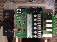
This is an old diy project - I started some years back and slowly proceeded to the final stage now 🙂 It is a fully digital loudspeaker. Schematic attached (SRC4392 as receiver and ASRC), TAS3103 as equalizer and TAS5518 as 3 band crossover and PWM driver for class D end stages.
It works somehow, however occasionally it happens that there is no sound. I tried to re-flash the firmware for Atmel controller, power on, power off several times and sometimes it works but after some time it stops working again (after a new power on). That is why I'm trying to investigate what can be wrong - started with SRC and recognized that there is no Data signal between SRC and TAS3103. So I'm digging deeper and found out that it is probably DIR part of SRC4392.
It works somehow, however occasionally it happens that there is no sound. I tried to re-flash the firmware for Atmel controller, power on, power off several times and sometimes it works but after some time it stops working again (after a new power on). That is why I'm trying to investigate what can be wrong - started with SRC and recognized that there is no Data signal between SRC and TAS3103. So I'm digging deeper and found out that it is probably DIR part of SRC4392.
If any interest in trying it, seems like it should be reasonably easy to tie RXCKO and RXCKI together since they are right next to each other at one corner of the chip.
Otherwise, Marcel's approach might work too.
May I ask what this is for? Going into a dac or something? If so, Sabre, AKM, etc.?
Also, is this a for a one-off DIY project, anticipated commercial application, other?
Those things may matter as to what ultimate solution would be good.
Attachments

...after some time it stops working again (after a new power on)...
Are you saying the failure always starts right after a power-on, but not after every power-on?
Correct, only during power on and only sometimes. Wasn't able to find out when it happens and what is influencing it. I always try to power on and off several times, then I re-flash the firmware to make sure it is ok. Connect from PC to make sure registers are configured as they should be... and after some time of tweaking it starts working again. Now it doesn't work for 2 weeks so I started diging into the details and recognized that LRCLK and BCK signals are ok as an output of SRAC4392 while PORTA data signal is not present.
Are you saying the failure always starts right after a power-on, but not after every power-on?
Okay, I see. Sounds like it might be a power/signal sequencing or rise time problem. SRC4392 has two power inputs, are they both running from 3.3v and start up at the same time? How fast is the rise time of the power when turned on (if too slow sometimes that could possibly affect some 'auto-reset at power-on' function)? When does MCLK start up after power-on?
Last edited:
Petr,
I'm not sure I understand the Clock structure here - what are you trying to achieve?
Are you expecting the Audio clock to be:-
1. Audio Clock Recovered directly from incoming SPDIF Clock (No ASRC)
2. Used in ASRC Mode, so Audio clock Fixed and determined by input Master Clock (from PLL1705)
I'm wondering if the device configuration is wrong, and works OK when input Data PPM clock Offset is close to the input reference clock, but with a larger input PPM Clock error the device does not lock, this would explain the "Random" working condition.
Last edited:
Thanks Mark. After power on the sequence is:
- all power supplies on immediately, MCLK applied to SRC4392 immediately
- delay (wait) 1 second
- configure external SRC4392 pins via microcontroller (CS0, CS1, /RST, MUTE)
- Reset SRC4392 through /RST pin (registers in default state)
- page select 7F 00, power off DIR, SRC, DIT, PORTA through register 01 00
- configure all SRC4392 registers
- power on DIR, SRC, DIT, PORTA through register 01 7F
When I check status of registers - ok, power supply - ok, PORTA output as mentioned before - LRCLK ok, BCK ok, data not ok, /LOCK pin high
Okay, I see. Sounds like it might be a power/signal sequencing or rise time problem. SRC4392 has two power inputs, are they both running from 3.3v and start up at the same time? How fast is the rise time of the power when turned on (if too slow sometimes that could possibly affect some 'auto-reset at power-on' function)? When does MCLK start up after power-on?
Thanks John. Clock is configured as follows:
- one common MCLK clock signal generated by PLL1705 - 24.576 MHz used for all DIR, SRC and PORTA (in master mode)
- input SPDIF signal 44.1- 192 kHz, output PORTA signal fixed 96 kHz
As I have issue with no data on PORTA I also tried to feed DIR directly to PORTA -in this case I use input SPDIF signal 96 kHz, output PORTA signal 96 kHz, MCLK for both of them. LRCLk and BCK signal as output of PORTA ok, Data signal on PORTS not present.
I’m still thinking how to isolate the problem by checking wheteher DIR only works fine -not sure how to do it - /LOCK pins shows high.
Petr,
I'm not sure I understand the Clock structure here - what are you trying to achieve?
Are you expecting the Audio clock to be:-
1. Audio Clock Recovered directly from incoming SPDIF Clock (No ASRC)
2. Used in ASRC Mode, so Audio clock Fixed and determined by input Master Clock (from PLL1705)
I'm wondering if the device configuration is wrong, and works OK when input Data PPM clock Offset is close to the input reference clock, but with a larger input PPM Clock error the device does not lock, this would explain the "Random" working condition.
That it only happens intermittently at startup is a big clue, seems to me anyway. Did it always do that from the time you first built it, or did the problem only start happening later?
Correct - when I apply power on it either works or not. It never happened during playing music - if it works after power on, it works all the time until power off.
I think it is the same all the time. Maybe getting slightly worse (more often) over the time.
I think it is the same all the time. Maybe getting slightly worse (more often) over the time.
That it only happens intermittently at startup is a big clue, seems to me anyway. Did it always do that from the time you first built it, or did the problem only start happening later?
Petr,
As your using DSP, I suspected as much that you would require a fixed audio sample rate and hence be using an ASRC so you can have fixed DSP coefficients...
Some devices require the Ref Clock stable before releasing the Reset line... wonder if this could be the issue.
The PLL1705 being a PLL Gen might need a few clock cycles to output s stable clock...
I wonder how you plan to keep the Channels in correct phase? with two separated ASRC / Reference clocks your going to have a hard time keeping the channels in correct phase... Phase matching between channels might be drifting...
I'm not sure how the TI ASRC works - its internal DPLL B/W etc... but I'd not be surprised to see inter-channel Phase wonder.. I've seen DAC designs where the designers have used ESS in dual mono configuration each with there own Master Ref clock and guess what - inter-channel phase wonder.... these DAC's where offered for sale!
Depending on the ASRC Rate estimator and DPLL loop B/W the ASRC might Phase lock OK to the SPDIF Clock, but this cannot be counted on.. Its really worth confirming that the audio output between your channels is correctly inphase under all conditions.
Thanks John. Clock is applied to SRC4392 through MCLK immediatelly after power on. To make sure everything is ok I wait 1 second after power on, reset SRC4392 and configure registers only then.
You are right that I need a fix output of 96kHz from SRC4392. That is why the flow within is DIR —> SRC —> PORTA. One common clock source MCLK for all 3 blocks.
As it sometimes doesn’t work I’m trying to find a root cause and therefore removed SRC first to go DIR —> PORTA (both using MCLK and fix 96kHz input and output). No output from PORTA. Not sure how to continue and fing out what is the issue. As mentioned before I can see /LOCK pin high - seems DIR is not locked.
Petr,
As your using DSP, I suspected as much that you would require a fixed audio sample rate and hence be using an ASRC so you can have fixed DSP coefficients...
Some devices require the Ref Clock stable before releasing the Reset line... wonder if this could be the issue.
The PLL1705 being a PLL Gen might need a few clock cycles to output s stable clock...
I wonder how you plan to keep the Channels in correct phase? with two separated ASRC / Reference clocks your going to have a hard time keeping the channels in correct phase... Phase matching between channels might be drifting...
I'm not sure how the TI ASRC works - its internal DPLL B/W etc... but I'd not be surprised to see inter-channel Phase wonder.. I've seen DAC designs where the designers have used ESS in dual mono configuration each with there own Master Ref clock and guess what - inter-channel phase wonder.... these DAC's where offered for sale!
Depending on the ASRC Rate estimator and DPLL loop B/W the ASRC might Phase lock OK to the SPDIF Clock, but this cannot be counted on.. Its really worth confirming that the audio output between your channels is correctly inphase under all conditions.
Do you see anything suspicious on any of the SRC4392 pins? Are all supplies stable and at the right voltage? Are the SPI signals and the external master clock free from excessive over- or undershoots? Is the SPI clock frequency within spec (that is, below 40 MHz, if I remember well)?
Edit: you use I2C, so the questions about SPI are not applicable. The answer is almost certainly yes, but are the 2.7 kohm pull-up resistors low enough for the speed you use?
Edit: you use I2C, so the questions about SPI are not applicable. The answer is almost certainly yes, but are the 2.7 kohm pull-up resistors low enough for the speed you use?
Last edited:
Thanks Marcel. This is definitely one thing to try for me:
- DIR using MCLK 24.576 MHz and generating RXCKO output
- PORTA using RXCKO generated by DIR as clock (instead of MCLK as I have it now)
However I'm not sure if it helps as the issue is probably with DIR which is not able to lock.
My valve DAC example just shows that the DIX4192 DIR (which is supposed to be compatible with the SRC4392 DIR) can work with the master clock as reference, that's all. I never checked the lock output, but as it is programmed to mute its output when out of lock, I would have noticed it if it didn't lock.
I checked:
- power supplies - correct levels, clean DC voltage
- MCLK frequency ok 24.576 MHz, good shape, no oscillations
- /LOCK and /RST high, clean DC voltage
- I2C bus, checked configuration of registers and everuthing is ok
There are 2 strange things happening but I believe these are not onnected to issue f not having output signal, or?
1. Although I set pins PF3 and PF4 of Atmel as low to define CS1 = 0 and CS0 = 0 it doesn’t work with SRC4392 address 0xE0 but only with address 0xE4 (meaning that pin CS1 is somehow forced high - although sw in Atmel is forcing is low)
2. When I read registers of SRC4392 all of them are ok - reading same values which are programmed. However there is one exception - if I try to read register 0x01 I’m getting value 0x00 while I programmed it for 7F. Furthermore after the read opperation of register 0x01 all registers are set to default value - seems like reading register 0x01 resets the SRC4392?
Do you see anything suspicious on any of the SRC4392 pins? Are all supplies stable and at the right voltage? Are the SPI signals and the external master clock free from excessive over- or undershoots? Is the SPI clock frequency within spec (that is, below 40 MHz, if I remember well)?
Strange; writing a 1 in the MSB of register 01 should reset the SRC4392, but reading it should not.
Do you wait for at least 500 us after the end of the reset pulse, per page 23 of the datasheet?
Do you wait for at least 500 us after the end of the reset pulse, per page 23 of the datasheet?
Yes I do wait 20 ms.
And I agree both behaviors described are strange - SRC4392 I2C address as well as reading reg 0x01...
And I agree both behaviors described are strange - SRC4392 I2C address as well as reading reg 0x01...
Strange; writing a 1 in the MSB of register 01 should reset the SRC4392, but reading it should not.
Do you wait for at least 500 us after the end of the reset pulse, per page 23 of the datasheet?
That's a pity...
No shorts between pins due to solder bridges or so? Or crosstalk due to long parallel tracks at very small distance? I2C interfaces normally have built-in spike filters, but I don't know about the other lines.
No shorts between pins due to solder bridges or so? Or crosstalk due to long parallel tracks at very small distance? I2C interfaces normally have built-in spike filters, but I don't know about the other lines.
I will do one more scope texting tomorrow.
However as I have two speakers - two PCBs with SRC4392 I can see the bahavior of incorrect I2C address as well as “reset” while reading reg 0x01 with both of them.
Also the occasional loss of audio signal in SRC4392 is happening with both of them (independently)
However as I have two speakers - two PCBs with SRC4392 I can see the bahavior of incorrect I2C address as well as “reset” while reading reg 0x01 with both of them.
Also the occasional loss of audio signal in SRC4392 is happening with both of them (independently)
That's a pity...
No shorts between pins due to solder bridges or so? Or crosstalk due to long parallel tracks at very small distance? I2C interfaces normally have built-in spike filters, but I don't know about the other lines.
- Home
- Source & Line
- Digital Line Level
- SRC4392 problem with DIR / SPDIF