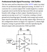
??? Doesn't matter it looks like an ordinary 3K transresistance I to V.
I think it does matter, I've been bitten by this, a unipolar current output DAC charges that 2n cap by the average current which leads to a large offset voltage at the output. Which may (or may not) be an issue. At least iirc this was the circuit.
Jan
I did this back in the day of the AD1862. The op-amp and network forms a damped two pole network (~500kHz or so) but the big cap ends up taking the transients passively so the op-amp never has to slew. There is some noise gain but the OP's post filter would take that out. This requires a little thought and there is room to tweak the values for a particular amp.
I built this into a demo card, the HF hash removal from DAC clock noise was also dramatically reduced.
With an ideal op-amp the big capacitor doesn't do anything. Are you sure the small resistor isn't supposed to be between the big cap and the negative input of the op-amp, with the small feedback capacitor feeding back straight to the negative input of the op-amp and the big resistor to the big cap?
The opamp is not ideal. At the requency range of the actual HF noise content spit out from the dac, the input node is a virtual inductance, because of falling open loop gain of the opamp.
C1 continues to have a low impedance towards ground. So conducts HF energy back to the common ground with the dac.
But the setup is a TIA with a strongly peaking noise gain. That peaking is damped by C2, which limits the rising gain at high frequencies. R2 separates the output of the opamp from direct capacitive load.
My doubt is.. any resonance between the undamped C1 and virtual inductance of the -IN?
Last edited:
With an ideal op-amp the big capacitor doesn't do anything. Are you sure the small resistor isn't supposed to be between the big cap and the negative input of the op-amp, with the small feedback capacitor feeding back straight to the negative input of the op-amp and the big resistor to the big cap?
No that is over simplifying, it is better to think of an ideal op-amp as having infinite Aol but an ideal integrator response limited by current speed capabilities. You are thinking infinite Aol and infinite bandwidth. As I said I built exactly what I published and it worked as expected, it does need optimization around a particular op-amp but there is a lot of literature on high source capacitance I to V's for photo-diodes.
Attachments
I did this back in the day of the AD1862. The op-amp and network forms a damped two pole network (~500kHz or so) but the big cap ends up taking the transients passively so the op-amp never has to slew. There is some noise gain but the OP's post filter would take that out. This requires a little thought and there is room to tweak the values for a particular amp.
I built this into a demo card, the HF hash removal from DAC clock noise was also dramatically reduced.
WOW! Just listening now...

any serie resistance CRCR (RotelSolution) even low as 47 ohm made dull sound but the solution to put only a cap in paralellel (1.8 nF polypropilene what I'm listening to now) between Pcm56 outputs and IV opamp inputs without any serie resistor made everything smoothed (i.e. less fatiguing) without loosing dynamic, soundstage and naturalness. I didn't put yet the suggested light RC network across the feedback cap...only a tiny 7pf....It will be next step....
My doubt is.. any resonance between the undamped C1 and virtual inductance of the -IN?
The circuit can be tuned to a critically damped two pole response which limits the Q of the noise gain. Typically this can be placed so far above above frequencies that post filtering easily takes care of it. There has been so much written about I to V's from high capacitance photo-diodes that I didn't see the point in rehashing it at the time.
No that is over simplifying, it is better to think of an ideal op-amp as having infinite Aol but an ideal integrator response limited by current speed capabilities. You are thinking infinite Aol and infinite bandwidth. As I said I built exactly what I published and it worked as expected, it does need optimization around a particular op-amp but there is a lot of literature on high source capacitance I to V's for photo-diodes.
As far as I'm concerned an ideal op-amp by definition has nullor properties, which is equivalent to having infinite voltage, current, transimpedance and transadmittance gain at all frequencies. Of course an integrator is indeed a more accurate approximation of a real op-amp.
I gather the small capacitor creates a (phantom) zero to stabilize the loop, but what is the small resistor for? Phase correction of the input-to-output transfer or keeping the high-frequency current out of the op-amp's output (or both)?
I think it does matter, I've been bitten by this, a unipolar current output DAC charges that 2n cap by the average current which leads to a large offset voltage at the output. Which may (or may not) be an issue. At least iirc this was the circuit.
Jan
Jan maybe I'm misunderstanding, a DAC can sit at 1mA out and go 0 to 2mA with signal so the I to V sits at the middle. It could also sit at 0 and go -1mA to 1mA like the AD1862 does on the data sheet. Both work fine here, the large offset is just splitting the supply in a single supply application.
I gather the small capacitor creates a (phantom) zero to stabilize the loop, but what is the small resistor for? Phase correction of the input-to-output transfer or keeping the high-frequency current out of the op-amp's output (or both)?
Sorry it does not do much in general, in the original it was a high frequency snubber for the particular op-amp. Sorry for any confusion.
Even an ideal opamp has to have some HF rolloff, otherwise there is no hope of putting it in a stable loop. The choice is between infinite DC gain (integrator) or finite DC gain (very high gain first-order LP filter). Use whichever model is easiest in the context.MarcelvdG said:As far as I'm concerned an ideal op-amp by definition has nullor properties, which is equivalent to having infinite voltage, current, transimpedance and transadmittance gain at all frequencies. Of course an integrator is indeed a more accurate approximation of a real op-amp.
Even an ideal opamp has to have some HF rolloff, otherwise there is no hope of putting it in a stable loop.
I don't see that, simply putting a frequency independent block of gain 1e6 into the equations yields trivial results, i.e. a perfect Sallen-key for example. There is nothing to create instability.
DF96, you are mixing up abstraction levels as far as I'm concerned. A nullor simply has vin = 0 and iin = 0 and vout = whatever it has to be and iout = whatever it has to be. Loop stability has nothing to do with it. At this level of abstraction there is not even any difference between positive and negative feedback, as 0 has no sign.
In any case, this is getting off topic. For real op-amps, Scott's circuit is very interesting.
In any case, this is getting off topic. For real op-amps, Scott's circuit is very interesting.
In any case, this is getting off topic. For real op-amps, Scott's circuit is very interesting.
It's good to realize where approximations are useful, in standard op-amp applications if the Aol is 2e6 or 10e6 is does not matter much but if you state the GBW is infinite then you remove any contribution from the amplifier to the response.
Interesting thing about putting a cap before the I/V opamp is that it was something that was getting fairly high on my list of things to try in order to help further improve sound quality on my own dac project. The sound quality improvement related issues that abraxalito has attributed to adding some filtering there (or the lack thereof with no filter) seems to have become much less of an issue with ES9038Q2M as (presumably) jitter approaches extremely low levels. At times when I can get jitter low enough to stabilize DPLL bandwidth at 1, I seem to get the same type of sound quality improvements as abraxalito describes hearing, and probably nearer to DAC-3 sound quality than ever before. The way it is kind of looking from here is like maybe a lot of the HF junk coming out of ES9038Q2M is jitter related HF distortion, so that as jitter is reduced so is the HF junk until eventually it becomes more or less a non-issue even without a filter.
The foregoing seems to be in keeping with what we know about Allo Katana as well. That other audio website that measures things found Katana to have the lowest jitter of any dac they have tested including DAC-3. With the so-called 'thd' output stage (that does not have a pre-I/V filter), it sounds very clean and clear (if running on linear supplies with film caps) very similar to how my modded dac does with DPLL stability at 1.
The foregoing seems to be in keeping with what we know about Allo Katana as well. That other audio website that measures things found Katana to have the lowest jitter of any dac they have tested including DAC-3. With the so-called 'thd' output stage (that does not have a pre-I/V filter), it sounds very clean and clear (if running on linear supplies with film caps) very similar to how my modded dac does with DPLL stability at 1.
It's good to realize where approximations are useful, in standard op-amp applications if the Aol is 2e6 or 10e6 is does not matter much but if you state the GBW is infinite then you remove any contribution from the amplifier to the response.
Sure, but the usual procedure for designing op-amps circuits is:
1. Assume the op-amp to have nullor properties and design the feedback network
2. Check the impact of the fact that the op-amp has no nullor properties. Usually, when the impact of finite gain-bandwidth product is large, the circuit is no good, because you then get sensitive to the open-loop behaviour and an op-amp is inaccurate and non-linear open-loop.
3. Make minor corrections for the non-ideal behaviour of the op-amp if needed
The circuit you've shown depends on the open-loop properties of the op-amp, reduces high-frequency loop gain over the band where the big cap kicks in and still works better than a more straightforward transimpedance amplifier. That's really interesting!
I would chose a more straigthforward transimpedance configuration in any moment, for the majority of the applications. The big capacity loading the TIA input is worsening all parameters of the circuit, and people spend a lot of time fighting this problem, in general. Speed, noise, and even stability is deteriorated.
The geniality of this move was that this badly performing circuit does one particular thing better: permits the use of less performant amplifiers still fullfilling their task adeguately.
The geniality of this move was that this badly performing circuit does one particular thing better: permits the use of less performant amplifiers still fullfilling their task adeguately.
When faced with the high freq. noise energy of a current dac output, even the best opamps are " less performers" than it would be needed.
Not so. Benchmark DAC-3 uses an ES9028PRO in current mode. They use LME49860 opamaps. DAC-3 is on the Stereophile A+ recommended equipment list, it sounds great, and has SOA measurements. There are ways to do it, if you can figure out how.
- Status
- This old topic is closed. If you want to reopen this topic, contact a moderator using the "Report Post" button.
- Home
- Source & Line
- Digital Line Level
- IV Opamp converter after DAC: which of the two circuits?