I am experiencing, very intermittent clicks and pops when listening. some days none at all.
I am using an 9038Q2M, separate VR, with typical xmos usb, Rpi as a streamer (ethernet to server), dac has a mains filter at the inlet.
I would like to know if this is still something that can be expected with these mobile dac chips or if it could possibly be down to my implementation?
I am mainly looking at sources of noise on my electrical network as a cause but would like to check here to try and rule the dac out.
Could be really useful do a list of the top DAC boards suggested for different type of projects.
Don't know if anyone has that much information on that many boards. Nobody I know of has gone through modding 50 different boards, let alone identified a top 50 out of possibly 100's of dacs they have experience with modding.
One option we didn't talk about that might be the easiest cheap path to a pretty good dac, and that might be to mod a low-ish cost Chinese AKM dac board. If you replaced all the components except the dac chip on a Chinese AK4493 dac board then it might about about as nice as the JL Sounds AK4493 board. The reason I say that is because there are a lot of cheap/fake components on low cost Chinese dac boards, just the way it is. That's why prices are so low.
The possibly good thing about cheap Chinese AKM dac chip boards is that one need not start upgrading all the components right away, or ever for that matter. If it sounds good to the owner then its good enough.
While its easier to get good sound out of AKM dacs verses ESS dacs, a good USB board (and or AK4137/AK4118 board for SPDIF) with good clocks adds to cost.
The nice thing about ESS dacs is a lot of stuff is built into one chip: ASRC, SPDIF receivers, etc. The bad thing is that its a lot of work to get the best sound quality out of them, which brings things back to being as complicated or maybe more complicated than a good AKM dac.
Any ideas yet about what you want to do? Forget the whole thing?
Just switched out an 80VA toroid powering the IV circuitry to a smaller 18VA EI transformer cause I wanted to use the 80VA for a desktop amp system. Something changed for the better. Superior imaging and better bass coherency and a slight touch more clarity in the upper midrange. Last time when I switched out a 30VA C core transformer to the toroid I noted better lows but this EI switch was surprising. It could also be that the relative phases of the output of many transformers could have been changed.
So many little things can change the sound!
So many little things can change the sound!
...Last time when I switched out a 30VA C core transformer to the toroid I noted better lows but this EI switch was surprising...
R-core transformers are usually best for dacs IME. One with a higher current rating than the minimum necessary may help bass response due to decreased voltage regulator input sag. The main reason for using R-cores is to help prevent AC line (line frequency harmonics/HF/RF) noise incursion into sensitive circuitry. Unintended/unexpected ground currents are often the culprits.
Last edited:
I am not surprised. Yes, all these 'particulars' are having an influence. Many times EI transformers block /filter better the power line noises.
Edit: also, the ringing in the secondaries of a toroidal is more agressive, at higher frequency, than in an EI..
A question: did You try Quasimodo the transformers?
It gave me extremely positiv results in my dac setup.
(too, apart from amplifiers)
Hats off to Mark!
Edit: also, the ringing in the secondaries of a toroidal is more agressive, at higher frequency, than in an EI..
A question: did You try Quasimodo the transformers?
It gave me extremely positiv results in my dac setup.
(too, apart from amplifiers)
Hats off to Mark!
Just switched out an 80VA toroid powering the IV circuitry to a smaller 18VA EI transformer cause I wanted to use the 80VA for a desktop amp system. Something changed for the better. Superior imaging and better bass coherency and a slight touch more clarity in the upper midrange. Last time when I switched out a 30VA C core transformer to the toroid I noted better lows but this EI switch was surprising. It could also be that the relative phases of the output of many transformers could have been changed.
So many little things can change the sound!
Last edited:
Just curious, are there measurements or objective listening evidence to support such opinion?The bad thing is that its a lot of work to get the best sound quality out of them, which brings things back to being as complicated or maybe more complicated than a good AKM dac.
Just switched out an 80VA toroid powering the IV circuitry to a smaller 18VA EI transformer cause I wanted to use the 80VA for a desktop amp system. Something changed for the better.!
Is replaced toroid standard type or one with static shield between primary and secondary windings (there is grounding wire) so called “audio grade” toroid?
Is replaced toroid standard type or one with static shield between primary and secondary windings (there is grounding wire) so called “audio grade” toroid?
It is a 20+ year old 80VA 18+18 Plitron with dual secondaries. No shield wires.
The EI is also a Hammond with 36VCT@500ma.
One thing we never did with AK4137 was to try a reclocker on its output. That would be implemented with a D-flip flop of the I2S signal before they come into the dac board, and it would be clocked by a divided version of the dac clock.
Hello Mark,
Well don’t be so sure about that. I received the ak4137 board this week and I did some testing(thd tests) with amanero, cronus and b3se. I didn’t manage to listen too much to the entire combo because was a bit busy ... and to be honest like I have already said I don’t trust my ears too much.
I will start a new thread these days and will post there exactly what I did and there will be also a few screen captures for thd measurements done with REW so keep tuned.
Best regards.
Hello Mark,
Well don’t be so sure about that. I received the ak4137 board this week.
Hi schultzsch,
When you get around to posting your results, please also let us know which AK4137 board you got if you did any mods to it. Thanks.
Hi schultzsch,
When you get around to posting your results, please also let us know which AK4137 board you got if you did any mods to it. Thanks.
I think it’s the same board as the one you have. No moods yet. Kept everything stock and made the measurements so later if I mood something I will have some data to compare with.
For the ones interested about this I will post a link here when the new thread will be posted, most probably over the weekend.
Attachments
JohnW,
Regarding XMOS programming, so far no one with the know-how has volunteered. I still feel that in the absence of an XMOS programmer, an external USB to I2S board should be workable. I have been using JL Sounds I2SoverUSb: I2SoverUSB - I2S over USB Audio
...which optionally works fine with external 45/49MHz clocks. It is limited to stereo rather than 4-channel operation, but that's probably okay to start with, at least it seems so to me.
Mark,
Sorry for dropping off the radar - I've basically dived head on into C++ programming that I need to move forward to finally complete various longterm projects - while I believe Python is a better choice for DiYers' I need to work with others in the industry and as such, most code is in C/C++...
IMO C++ is a horribly over complex language - with needlessly complex syntex requirements and a truly horrid / steep learning curve... when looking at the clean elegance of python code I dont understand why C has to be so cryptic...
IMO C/C++ is the "bureaucratic" programming language, while python strips away this needless complexity... 90% of the time Syntax will be the cause of any errors with C++... HORRID!
Still my C++ code makes me look like a "Pro" and that I know what I'm doing - but I still really dont - and this scares me!!!
Oh yes, and compared to the simplicity of Serial Comms - I2C is a pig communications interface...
A DiY AKM project is still very much in the back of my mind...
Last edited:
Hi John,
Thank you for the update. Perhaps those of us less busy than you and with some remaining interest should continue thinking about working on a basic AK4499 project...
Regarding C/C++ sorry to hear about your woes. Programming languages have gotten huge to the point many programmers can't remember all the options built into one language, let alone multiple languages. Hopefully, you have a more experienced programmer around for times when some consultation might be helpful.
Regarding I2C, it isn't too bad is it? Well, that assumes you don't have to write your own I2C library. Mostly, its like anything else: It can seem difficult until reaching a point of understanding that comes with experience, then it seems obvious")
Thank you for the update. Perhaps those of us less busy than you and with some remaining interest should continue thinking about working on a basic AK4499 project...
Regarding C/C++ sorry to hear about your woes. Programming languages have gotten huge to the point many programmers can't remember all the options built into one language, let alone multiple languages. Hopefully, you have a more experienced programmer around for times when some consultation might be helpful.
Regarding I2C, it isn't too bad is it? Well, that assumes you don't have to write your own I2C library. Mostly, its like anything else: It can seem difficult until reaching a point of understanding that comes with experience, then it seems obvious
Last edited:
I think it’s the same board as the one you have.
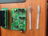
The pic of your AK4137 looks like it might be missing a part. The board I have of that style has one more small pcb with a single momentary push button on it. The button board plugs into a small connector on the display board. The button is to configure AK4137 operation and select digital audio input sources.
EDIT: Also, if you don't already have a pin header kit and crimper, you might want to consider getting something like: WayinTop Connector Crimping Tool Kit Crimper Plier 2.54mm Header Male Female Crimp Pins Terminals Housing 1 2 3 4 5 6 8 10 Pin and 40pin 1.27mm Ribbon Cable FC/IDC Jumper Wire 1M (Crimping Set) - - Amazon.com
A couple of comments about using pin headers for digital audio: (1) ribbon cable conductors tend to be brittle and fatigue break easily when used with pin insert and shell type pin header connectors. I usually prefer to use #28 silver plated teflon wire with JST connectors, maybe such as: PTFE Teflon Silver Plated Copper Hook-Up Wire or Pairs 24/28/30 AWG 3m/10' | eBay
...and, (2) for I2S and clock pin (and their associated grounds) header cables I found that using other than gold pins can cause audible jitter problems. At one time low cost gold flashed pin header kits were available from Amazon or ebay, but haven't seen any for a long time. Gold JST pin inserts (both male and female) that work with standard shells are available from suppliers like Mouser and Digikey, but they are sold by the individual pin and are not cheap. Don't know what to do about that but only use them in critical locations.
Also, best to get in some practice crimping and or soldering pins before using gold inserts. It takes some practice to do reliably. I could offer some tips later when the time comes.
Last edited:
Regarding I2C, it isn't too bad is it? Well, that assumes you don't have to write your own I2C library. Mostly, its like anything else: It can seem difficult until reaching a point of understanding that comes with experience, then it seems obvious
Trouble is many devices support the "physical" I2C BUS but dont conform to the protocol - so I have indeed ended up having to edit standard I2C library to cater for these edge cases
When buffers overflow etc. it gets complex quick and I'd be stuck without a logic analyser to see whats really going on..
Last edited:
Hi John,
Thank you for the update. Perhaps those of us less busy than you and with some remaining interest should continue thinking about working on a basic AK4499 project...
Mark,
I'd like to work on the dual IC solution from AKM (the part numbers slip my mind ATM) - rather then a AK4499 design...
I'd like to work on the dual IC solution from AKM (the part numbers slip my mind ATM) - rather then a AK4499 design...
Me too, but they are unobtainium at the moment. Can't even get a full datasheet for one of them.
How do you measure jitter introduced by the connections between the boards?
Jitter can sometimes be inferred from Sabre dac DPLL bandwidth stability. Lower stable setting values imply lower jitter of incoming I2S signals. Its kind of an indirect measure, but it works if jitter levels are within the range over which DPLL bandwidth is adjustable. The problem with noise related jitter is that it is nondeterministic and therefore doesn't show up as FFT spurs using J-Test.
I might add that correlating Sabre dac sound quality with DPLL numbers is also way to start understanding what jitter can sound like.
Last edited:
- Home
- Source & Line
- Digital Line Level
- ES9038Q2M Board