The replay equipment manufacturers do.Who cares,
Even more disappointed if you already spent a lot and likely be angry at the one who scammed you into it.But yes, I agree I would be disappointed to learn that my passionate brunette is just a trivial coloured blonde 🙂)
What criteria do you use for judging the performance of replay equipment?The replay is the performance. The performance is the replay.
What criteria do you use for judging the performance of replay equipment?
Does it please me. Or, as 5th Element might put it, does it make me happy.
That would be called "self-fi". Then there is "hi-fi" when it comes to audio reproduction.Does it please me.
Guys,
This thread is called ES9038Q2M board.
There was another thread opened for that kind of discussions in the lounge...
Do we have to call in the moderator in every 3 weeks or are some posters here able to find their way by themselves?
Claude
This thread is called ES9038Q2M board.
There was another thread opened for that kind of discussions in the lounge...
Do we have to call in the moderator in every 3 weeks or are some posters here able to find their way by themselves?
Claude
Gentlemen,
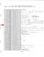
Because of the need to control the device registers in order to set PLL bandwidth and other things, a sample $10 ebay logic analyzer printout is attached showing I2C bus bootup activity of a Chinese board. In particular, I would focus attention on the line with a red arrow to the left and the following line. That is where the Chinese MCU enabled the device to start playing sound, an apparent quirk required for the particular chip and not well documented anywhere I have seen.
Because of the need to control the device registers in order to set PLL bandwidth and other things, a sample $10 ebay logic analyzer printout is attached showing I2C bus bootup activity of a Chinese board. In particular, I would focus attention on the line with a red arrow to the left and the following line. That is where the Chinese MCU enabled the device to start playing sound, an apparent quirk required for the particular chip and not well documented anywhere I have seen.
Attachments
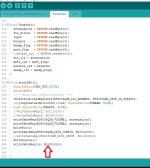
Mark, it took me 3 hours, back in March, to figure out why my DAC doesn't start. I removed the Chinese STC chip and I have replaced it with an ESP32 based board.
My DAC board is the blue one, so its controller chip was STC. I have started to learn how to program it, but a got bored after a couple of hours.
I have finally found (by chance) that bit 6 from register 14 should be "1": soft start when locked. If this bit is "0", always soft start, the DAC won't play.I don't know why!
Attachments
Hi Thorp, Its not documented in some versions of the datasheet, and its documented incorrectly in other versions (one of them says bit 7 must be 1, which is wrong). As you found out correctly, its bit 6. I found out by watching the MCU boot up the dac, as per the printout.
Apparently they didn't want it to be enabled by default for applications like cell phone audio. The documentation for the part is pretty sparse, don't know why they couldn't at least make it more accurate.
Apparently they didn't want it to be enabled by default for applications like cell phone audio. The documentation for the part is pretty sparse, don't know why they couldn't at least make it more accurate.
Last edited:
One of the interesting things that can be done with the registers, and I think Allo is planning to let users do this with their newest board, which is use the harmonic distortion compensation registers for adjustment to the user's listening preference, or for practice learning how to hear small distortion. IME it takes a very clean power amp and very clean speaker in the very near field to hear that smallest distortion change. Can be pretty challenging, but IMHO a very good practice tool for listening skill training.
Of course, for sound quality purposes, PLL bandwidth is probably the most important register. Only exception would be if one's output stage has some 2nd or 3rd order HD one would like to minimize. A perfect output stage won't need it, but many of them can benefit. Benchmark Media adjusts the distortion comp. registers individually for every DAC-3. Allo did the same with their Katana dac.
Of course, for sound quality purposes, PLL bandwidth is probably the most important register. Only exception would be if one's output stage has some 2nd or 3rd order HD one would like to minimize. A perfect output stage won't need it, but many of them can benefit. Benchmark Media adjusts the distortion comp. registers individually for every DAC-3. Allo did the same with their Katana dac.
Last edited:
Because things are so slow in the forum these days, I was wondering if people would be interested in learning/discussing more about controlling dac registers with Arduino (or RPi). Besides some immediate value it could be a good prelude to discussing synchronous mode dac design, and possibly good for some other semi-advanced dac modding topics.
Depends on what folks are interested in and on how much people already know. For example, not sure who did/didn't understood what they were looking at when I posted a logic analyzer dump, or, say, when Thorp posted some dac configuration code.
If any interest in possible topics, please let me know. Would also need to know more or less where people are at now in terms of what they do understand to their own satisfaction verses what they maybe don't understand well enough to feel comfortable with.
Gentlemen,
Because of the need to control the device registers in order to set PLL bandwidth and other things, a sample $10 ebay logic analyzer printout is attached showing I2C bus bootup activity of a Chinese board. In particular, I would focus attention on the line with a red arrow to the left and the following line. That is where the Chinese MCU enabled the device to start playing sound, an apparent quirk required for the particular chip and not well documented anywhere I have seen.
So you are saying that you have to send this register in order to get the chip to work properly?
From what I can see this is register 14 (decimal, as they are numbered in decimal in the datasheet). So this regiuster is set to 0b01000010, which is the default according the datasheet - this is indeed interesting. I would have assumed that I don't have to touch this register at all if I want default behaviour.
Are there more quirks like this?
Regarding your latest post: I'm currently developing a new PCB for the 9038Q2M and will have to get into programming the chip eventually. Regarding your question about the prior knowlege: hands on - 0, in theory: did read the datasheet several times.
Do we really have to be so secret about the registers here? A google search for "es9038q2m datasheet" immediately turns it up. So the information can be considered as publicly available. On top of that none of us signed a NDA (I assume). Maybe someone with more knownledge about the law can chime in here?
So you are saying that you have to send this register in order to get the chip to work properly?
From what I can see this is register 14 (decimal, as they are numbered in decimal in the datasheet). So this regiuster is set to 0b01000010, which is the default according the datasheet - [...]
No, register 14 is 0b00001010 default and the DAC won't play.
You have to set it 0b01001010 in order to hear some music.
Aha, it seems that is possible to also make the DAC working by setting register 14 to 0b10001010. I will try this setting.
Last edited:
Thanks for thew clarification. datasheet clearly states the default as 0, I dind't read correctly. But it doesn't tell that this has to be set to 1. So thanks for the info again Thorp and MarkW!
Are there more quirks like this?
Not exactly. Trying to turn off ASRC for synchronous operation can be tricky, but that's not how ESS expects most people to use its dacs (although IME the dacs sound better/less-distorted with ASRC off).
One of the big problems with these dacs is the RF coming out of the analog outputs and passing through the I/V opamps. Probably the main reason some people end up using transformers for I/V, even though transformers bring their own problems.
Last edited:
I have tested all 3 combinations for bit 7 and bit 6 of register 14.
0b1000xxxx, 0b0100xxxx and 0b1100xxxx.
They all work.
Ha-ha, it's nice ESP32, I don't even need to open the DAC case, to upload the new sketch, since it can be done via WiFi.
0b1000xxxx, 0b0100xxxx and 0b1100xxxx.
They all work.
Ha-ha, it's nice ESP32, I don't even need to open the DAC case, to upload the new sketch, since it can be done via WiFi.
Not exactly. Trying to turn off ASRC for synchronous operation can be tricky, but that's not how ESS expects most people to use its dacs (although IME the dacs sound better/less-distorted with ASRC off).
One of the big problems with these dacs is the RF coming out of the analog outputs and passing through the I/V opamps. Probably the main reason some people end up using transformers for I/V, even though transformers bring their own problems.
It would be nice, if you could explain these problems in detail. That's exactly what we had in mind. But let's be sure we're on the same page regarding the nomenclature here first.
By disabling ASRC you mean to disable the DPLL? So the ASRC becomes an SRC essentially. is that correct?
I have tested all 3 combinations for bit 7 and bit 6 of register 14.
They all work.
Interesting. I didn't recall bit 7 working, but I guess my memory could be mistaken. Wouldn't be the first time 🙂 The way its supposed to work is bit 6 ramps up the analog outputs from ground level up to AVCC/2 volts (when dac is locked; lock bit = true). Outputs should return to ground when not locked. Ramping up to AVCC/2 as configured by bit 6 should not work when bit 7 is 0. Bit 7 supposedly initializes and ramps up the outputs to AVCC/2, and supposedly must be set to 1 for the dac to have analog outputs at all. IIRC what actually happens is the outputs ramp up to AVCC/2 and stay there if reg address 14 data is 0x42.
By disabling ASRC you mean to disable the DPLL? So the ASRC becomes an SRC essentially. is that correct?
With the dac otherwise set to operate (with asrc_en=0) in either (1) 128_fs synchronous mode, or (2) in 128_fs master mode, setting DPLL bandwidth = 0 disables DPLL and ASRC. No sample rate conversion is performed, as none is needed. However, if the dac cannot obtain lock (lock bit = 1) then setting DPLL to 0 will mute the output. Reasons for not obtaining lock include I2S jitter or slow I2S signal rise times. If necessary, a reclock/relatch stage may help clean up I2S signal quality before going into the dac chip so as to more reliably obtain lock.
Regarding RF coming out of the dac analog outputs, the first question is whether or not the I/V opamps can handle it without distortion for all sample rates that may be used. I didn't look at the RF closely with ES9038Q2M but I have seen and heard symptoms of it being there. (I did manage to measure it coming out of AK4499 I/V opamps.)
Symptoms include opamp heating not accounted for by audio power output, and increased distortion. It may or may not be possible to see the distortion with an FFT (if, say, it does not result in a stationary nonlinearity). One thing that seemed to work pretty well for my 2nd modded ES9038Q2M dac was to put the I/V opamps a few inches away from the dac chip and run twisted pairs of wire wrap wire from the dac +- outputs for each channel along the ground plane between the dac chip and the I/V opamps. Acted like a distributed filter, but not with too much capacitance that would cause gain peaking in the I/V opamps. No excess heating was observed in the I/V opamps with the twisted wires.
To see the I/V output RF with AK4499 I used a fast scope that could sample at 2GHz. Since it is so fast it can do sweep averaging and or dot averaging. Dot averaging is the one to use. It means for one horizontal sweep of the scope, the A/D has time to take several acquisitions at each sample point before moving on and doing the same thing for the next sample point. Random noise can thus be attenuated for a single sweep with a non-repetitive signal. Syncing the scope with the BCLK, MCLK, LRCK, etc., and looking at the I/V outputs with dot averaging showed the RF on the I/V outputs. It also let me trace the RF out of the dac into a headphone amp, and out the headphone jack. There was a very low level 2MHz being fed into the headphones (with the dac operating in 32/44 playback mode). Of course, the headphones didn't care, but RF running through a whole reproduction system can have unpredictable consequences on sound quality.
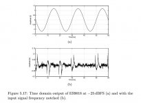
With Sabre dacs it is also ideal to tune the I/V feedback network to try to minimize hump distortion (which occurs at low-ish signal levels). The actual time domain distortion signal may be observable with a scope at high gain if the I/V output or dac voltage mode output is run through a notch filter before going into the scope. When ESS did that measurement, IIRC they used a 50Hz sine wave and a 50Hz notch. Probably possible to see the higher order harmonics more easily if using low frequency test sine wave. A pic of an example ES9018 notch-filtered distortion waveform attached below.
Attachments
Last edited:
Interesting comment in another thread: https://www.diyaudio.com/forums/dig...ing-dacs-sound-quality-fft-2.html#post6200566
In addition to what it says there, I find that radiated RF (clock harmonics associated with clock rise-time) as well as conducted RF can be factors affecting sound quality. Whether the RF affects I2S signals before they go into the dac or whether it affects the dac chip directly, it helps to put clocks where they cause the least audible distortion effects.
So, for example, if using clocks on a USB board or a USB board at all, I keep its ground plane side pointed toward the dac chip and I2S signal traces. Turning the USB board around to face the dac chip has an audible effect.
However, and its a big 'however,' most dacs are layered with sources of distortion all acting at once, some masking others, etc. And they have noise that masks some of the distortion. Finding little sources of distortion and fixing them one at a time can be a slow and tedious pursuit. It helps tremendously to have a better dac than you hope to make on hand to use as a listening reference. Chord Hugo TT 2 might do it. Buy one to use as a reference dac, write it off as a test instrument or sell it when done with it. If you are in business (I am not, but I know someone who is... 🙂 ) you are probably aware of the options.
- Home
- Source & Line
- Digital Line Level
- ES9038Q2M Board