Mark, what is the latest incarnation of the 4499 right now?
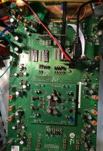
Right now its sitting inside a computer case on the bench. There are a couple of bench supplies powering it, one for +-15v, and the other for +8v. Both bench supplies and two computers are all plugged into separate ports of an ebay Monster HTPS 7000 MkII power conditioner (required for best sound quality at this point). The +-15v rails each have about 100uf of parallel film caps to ground. (Film caps mostly seem to be helping OPA1612 I/V opamps sound their best.)
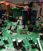
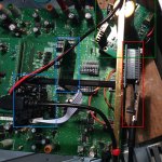
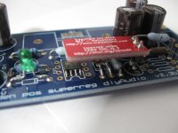
Below are some pics. A top view inside the computer case, side view showing the busy end, and a top view of the busy end showing the USB board and sample rate indicator board in the blue areas, Arduino (with no wall wart anymore) in red, and in green a Chinese dual LT3042 board supplying +5v and +3.3v locally.
The USB board happens to be the diyinhk one, but could be the JLsounds one would have a bit more reliable driver. Haven't decided on that yet. Master clocks are NDK SDA series on USB board. The USB board is suspended right over the I2S input connector with the ground plane side facing towards the dac chip area.
A brass frame was constructed to hang stuff on using existing holes at the corners of the eval board.
The I2C input is directly below the Arduino.
The purpose of the LT3042 board is to get most of the local digital regulators on the dac board separated from the +15v rail, from which they otherwise would receive power by default. (The power supply change helped clear up sound quality noticeably in terms of improved clarity.)
The analog output is taken differentially into a Neurochrome HP-1 ultra-low distortion headphone amp. Headphones are Audeze LCD-X. I believe the HP-1 uses a differential receiver for the balanced input. I haven't checked, but it might be a That Corporation part.
DSD512 is provided by a powerful desktop computer, one of the two computers powered by way of the power conditioner. (A fair amount of time has been spent troubleshooting and sorting out computer, HQplayer, and USB board driver issues.)
Slowly, I am working my way down the board towards the dac analog out power supplies, and to where there needs to be some kind of dedicated balanced to single ended converter circuit added. (A preliminary test using a dac output stage board, not one I made, just the differential summing part and using OPA1612 didn't sound as good as the HP-1 differential input, so have to find out why.)
At the moment, I am thinking about what I want to try doing with the Reference Voltage Jung regulator supplies. The dac sounds quite good as is, so this is getting more into the experimental realm where I don't know if any changes will make it sound better or not, but I hope to find out.
Also, thinking about whether or not there will be an ESS hump type issue, and if so whether the same type of solution might work here.
Attachments
Last edited:
Here are a couple of pics from my slowly being constructed Jung SuperReg for AVCC using the LTC6655s. The LTC6655 module is inverted and connects directly to the Jung Super Reg board. I might fire it up this weekend if I get a chance. The op amp driving the low voltage is the AD8031 as suggested by Didden. This will be connected with remote sense via coaxial cables to minimize noise. It should be interesting how this compares when replacing a Sulzer Jung AVCC supply using the AD817.
Attachments
Last edited:
Over the months, I've experimented with powering the Chinese XMOS USB board with different power supplies. Though I had heard about this, I did not think it would be worthwhile. However what happened is that I had to move my PC a bit and to do so quickly I used a different USB cable and then something changed very subtly but was obvious. I then reused the cable before and indeed it was noticeable...like rolling op amps. The better sounding one was the thicker one. I listened over a period of weeks. It was now obvious which was which once I clued in to what I was listening for. So I then made up a USB cable where the 5V could be powered externally therely eliminating the 5V from the PC. This is what I found an LM317 gave a very warm and smooth sound but imaging fell flat and lost a bit of transparency. The chinese LT3042 board was too slow for startup and the XMOS would not boot properly or reliably. I then used one channel of this power supply which appears to be a variant of the Sulzer using FETs. HIFI DAC Power Board Fever DAC Power Supply Module +- 12V 5V replace LT1963AEQ | eBay This restored the imaging and the warmth was returned to neutral according to my ears. This surprised me completely but it perhaps was not the cable itself per se but the delivery of the power and whether the power was clean that really mattered. The noisy power was possibly messing up the oscillators on the XMOS. I ended up using a wall wart supplying 9Vac to the 5V section of the board. I will break out the 2 12V sections for my Headphone amp.
[DIY] TNT 221 USB Y-cable [English]
[DIY] TNT 221 USB Y-cable [English]
Last edited:
Mike,
Does your dac board have an ES9028PRO or an ES9038PRO dac chip? If the former, it looks like two AD797 opamps can be used for AVCC buffering. Just don't use film caps on AD797 rails. My test board for ES9028PRO uses Jung regulators for AD797 +-15v. The +-15v for OPA1612 opamps is provided by another regulator board and has film caps on the rails. That particular project still needs other work though, it is set aside for now while AK4499 is the focus.
Does your dac board have an ES9028PRO or an ES9038PRO dac chip? If the former, it looks like two AD797 opamps can be used for AVCC buffering. Just don't use film caps on AD797 rails. My test board for ES9028PRO uses Jung regulators for AD797 +-15v. The +-15v for OPA1612 opamps is provided by another regulator board and has film caps on the rails. That particular project still needs other work though, it is set aside for now while AK4499 is the focus.
Last edited:
I have the 9028pro BUT it has a single rail for L&R AVCC. I'm always hesitant to subject the op amp to heavy currents as that area is always where op amps are weakest and misbehave the most. The 9038pro is supposed to use 4 times the current of the 9028pro so in theory even one AD797 should work. Even one channel of an AD1622 will easily do the trick.
For example, most headphones will work using the output of say a 5532 if not driven hard. However, if one puts a current buffer the sound totally changes. Can one infer it is the output section of the op amp that is misbehaving with higher currents? I suspect so.
I'm more excited about trying my AD1622 as an HPA using a PCB measuring less than 1 square inch!
Last edited:
I have the 9028pro BUT it has a single rail ...
Oh, okay. Never mind.
First I measured the current draw at the input of the dual ADM7150 board I have while using it to supply both AVCC_L and AVCC_R. Based on that, one AD797 should be able to handle either left or right AVCC, but probably not both at once. It may have been a moderately heavy load, but the output voltage doesn't change much. Sounded much better than ADM7150 even with the latter having some tweaks.
Last edited:
Tom's hp1 uses an opa1612 for the differential Input on each channel.
Interesting. Do you have a schematic?
Thanks everyone for replying me. A few more questions if I may.
Mark, could you please tell more about possible options of getting SPDIF from I2S? The Khadas board is very attractive for my project indeed.
What is a benefit of using a volume regulation on DAC’s and not in the miniSHARC itself? Would that also be necessary to have in case of using the Khadas boards via SPDIF? In case a separate controller is needed as well to regulate volume, it would probably be the easiest (not the cheapest though) for me to order the assembled solution that Audiophonics offer here:
MINISHARC CONTROLLER -Integrated DSP - Preamplifier DAC Network player - Audiophonics
Mark, could you please tell more about possible options of getting SPDIF from I2S?
I would suggest to carefully study an SRC4392 data sheet. I am familiar with how to use it and program it, so I can likely answer any questions. http://www.ti.com/lit/ds/symlink/src4392.pdf
What is a benefit of using a volume regulation on DAC’s and not in the miniSHARC itself?
A proper digital volume control has to be dithered. The dac does that. Don't know about the Sharc chip, but maybe it does. Please see: http://www.esstech.com/files/3014/4095/4308/digital-vs-analog-volume-control.pdf
Would that also be necessary to have in case of using the Khadas boards via SPDIF?
I assume the programmable XMOS chip configures the dac chip to automatically detect and play anything appearing at the SPDIF input, at least if no other inputs are in use.
In case a separate controller is needed as well to regulate volume, it would probably be the easiest (not the cheapest though) for me to order the assembled solution that Audiophonics offer here:
MINISHARC CONTROLLER -Integrated DSP - Preamplifier DAC Network player - Audiophonics
Maybe. Its starting to get expensive enough that other solutions may start to look more attractive. One ES9028PRO dac chip can handle eight channels of I2S, and it is possible to do it with quite a bit better sound quality than Tone Board does. Then again, maybe that MiniSharc Controller thing is a good deal, but it probably won't sound as good in all ways as a pretty good (although probably not exceptional) single stereo dac costing about the same and used with passive crossover speakers, or a pretty good stereo dac used with good analog electronic crossovers and minimal analog corrective EQ. The latter situation may be okay though, since corrective EQ often sounds better if not overdone.
Last edited:
Theres a block diagram on the ASR review thread for the hp1.
Thx for the tip.
I would suggest to carefully study an SRC4392 data sheet.
Actually, simple SPDIF transmitters that could accept I2S from a Sharc and output SPDIF to a Khadas Tone board are available. Its not necessary to get as complicated as SRC4392 just to send SPDIF. For example: http://www.ti.com/lit/ds/symlink/dit4192.pdf
Thanks for your help and support Mark!
I am still tearing apart looking for a solution. On one hand, I am interested in all this and it would be a great learning exercise to modify the modules and build an own dac; and save some $. On the other hand, I have a pretty tough family situation now and barely have time for this, while the system is standing without use.
I have also found some cheap boards that convert I2S to SPDIF such as for instance these:
I2S to SPDIF Coaxial Fiber Output Board/ IIS Input Coaxial Output 44.1K~192K | eBay
I have no idea about their performance though.
Anyway, even if I got these or similar boards and connected the sharc to Khadas, there is still an issue with volume control, right? Here is what I found about the minisharc from forums:"Channel and master volume settings are adjustable from the plug-in, which runs at 32 bit floating point resolution. Metering is also within the plug-in software GUI, unless you feed your digital audio though external hardware with meters."
Here I found another potential DAC solution with great specs:
Okto Research modules
Unfortunately, their modules are obsolete as well, and the only 8-channel option available is the DAC8 PRO which does not have I2S inputs.
I have also found some cheap boards that convert I2S to SPDIF such as for instance these:
I2S to SPDIF Coaxial Fiber Output Board/ IIS Input Coaxial Output 44.1K~192K | eBay
I have no idea about their performance though.
Looks like it might use the chip I just linked to in my last post. If so, its a good part.
Anyway, even if I got these or similar boards and connected the sharc to Khadas, there is still an issue with volume control, right?
True. The volume control in Sharc is probably no better than the digital volume control in Windows. If so, digital resolution would be lost as the volume is turned down. Probably better to use a good 6-gang pot volume control somewhere between the dac and the power amps. Of course, a pot should be buffered if needed depending on the particulars of how it would be driven and loaded.
Here I found another potential DAC solution with great specs:
Okto Research modules
Unfortunately, their modules are obsolete as well, and the only 8-channel option available is the DAC8 PRO which does not have I2S inputs.
AckoDAC probably makes one, no idea on price though. They use an ADM7154 LDO for AVCC last time I checked, not the best IME (but maybe acceptable for most listeners). AckoDAC
Also, when testing and advertising dacs, its possible to make a 1kHz FFT look very good without the sound being that great with music. Its simply not an adequate test to fully characterize a dac.
Might be possible to hack into Octodac to access I2S, don't know haven't seen enough of the inside of one.
Or, it might be possible, perhaps with linux, to send out stereo digital audio to a Sharc, bring it back in digitally at 6-channels, then route those out via USB to an Octodac. My understanding is that Linux is much more flexible in that way vs Windows, but haven't used Linux for advanced audio routing myself.
Last edited:
Just noticed there are two AK4499 eval boards in stock at Digikey, but they are expensive. Probably no surprise given the size and complexity of the board.
That's round about what I expected - ouch!
Hi Antonfazar,
I had lot of similar ideas about multichannel applications. At the moment I use nanodigi board with SPDIF in and outputs. The DACs are 2 of here described es9038q2m modded boards for mid and highrange and a 24 audaphon dsp for subs and DBA. I controle volume digitally via spotify app or sonos system that feeds the nanodigi via SPDIF - very happy with sq!
I tested before some solutions with i2s from Raspberry pi HAT with hifiberry DAC+pro as i2s source which I also fed into the cheap i2s to SPDIF board you mentioned above - worked quite good, but later some crackling noise occured - not sure what the reason was. I then used an Allo digione which I sometimes use as source instead of the sonos.
the octo research thing looks very interesting and the raw board should have an i2s input, no? They also talked about a DSP option with minisharc or nanosharc, but seems it was not followed. Dont know why there are not more multichannel DAC solutions to find with es90X8pro chips on the market as they are 8 channel devices..a pitty.
The audiophonics solution seem to use the DACs for volume controle as octo research does with es9028pro chip.
if converting minisharc i2s outs to spdif, I saw several applications now, where the i2s clock signals are buffered first, as LR clock and Bitclock are shared for all 8 channels- (why) is this necessary?
Sorry if too much OT...
Last edited:
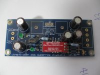
PCB (AVCC_LR)
*.json project files in zip.
There is still something you could do to improve your layout!
If you are using a 2 Layer PCB I would add VIAs for connecting GND between both layers. Use as much VIAs as possible!
A GND pin on the output side would also be good.
Both capacitors on the input can be rotated so that C1 is as close to the input pins VCC and GND as possible. You can place C2 between C1 and the supply pin of the opamp, if there is enough space left.
And why don't use the cap for C4 and C5 as you used on the input?
- Home
- Source & Line
- Digital Line Level
- ES9038Q2M Board