Any idea of the price range, Mark?
Not yet.
I'm hoping to make a start on the I/V and I have a question on the selection of resistors/capacitors on the -ve feedback loop. I can see on Jens' design he's using 470pf and 1.27k, on ESS application note 100pf/272 and on Mr Slim's 330pf/820. How are these determined?
The resistor is chosen first to give a desired I/V stage output voltage swing. The value is chosen according to ohm's law, R = E/I, where E is the peak output voltage and I is the maximum dac output current. There is also a DC offset that has to be added which is Vref = AVCC/2.
The cap should be NPO or C0G, and is chosen to give a particular time constant in combination with the resistor. tau = RC. That sets the first filter corner frequency.
There are some tradeoffs involved with the resistor value. If we keep it small-ish (such as 820-ohms for ES9038Q2M), the fact that there is a Vref offset voltage can used to bias the I/V amp to always run class-A. Since Vref=AVCC/2=1.65v for Sabre dacs, if we keep the I/V output swing to less than +-1.5v, the opamp output will never go below ground and will be running class-A.
On the other hand we could use a bigger resistor to get more voltage output from the first stage, if we think that would be of more value for our needs.
Thanks Mark, I really appreciate your response.
..why plt with AK4137 can not convert to dsd512, although it has a generator of 22.579MHz.
It can output DSD and half its own clock rate, and maximum clock rate for AK4137 is around 25MHz. That means 12.5MHz DSD256 is its practical limit.
Thought I might mention that for the ES9028PRO dac I am preparing at this point, I decided what I thought was mostly holding it back as of a couple of days ago was the Trident-AVCC power supply (even running it with 7v input and with 33-ohm load resistors). To find out, I built an AVCC board much like the one we recommend in this thread, in fact I used the same schematic. To meet the AVCC current requirements of ES9028PRO, I used dual AD797 opamps running off their own dedicated +-15v power supply. I find that I definitely prefer the opamp regulator again in this situation. A good finding, I think, for those that went ahead and built the recommended AVCC board for dac modding from this thread. For those preferring the simplicity of a pre-built AVCC solution, I think I can say that Trident-AVCC can do pretty well, and much better than stock, running from 7v input power and with a 33-ohm, 1/2-watt load to ground for each channel. Please remember, if considering running Trident-AVCC from 7v input, to read the part numbers on the ADM7151 chips and make sure that is what you actually have, and that they are therefore safe to run at more than 5v input. Some ADM715x family regulators are limited to a 5v maximum input level.
Last edited:
Thought I might mention that for the ES9028PRO dac I am preparing at this point, I decided what I thought was mostly holding it back as of a couple of days ago was the Trident-AVCC power supply (even running it with 7v input and with 33-ohm load resistors). To find out, I built an AVCC board much like the one we recommend in this thread, in fact I used the same schematic. To meet the AVCC current requirements of ES9028PRO, I used dual AD797 opamps running off their own dedicated +-15v power supply. I find that I definitely prefer the opamp regulator again in this situation. A good finding, I think, for those that went ahead and built the recommended AVCC board for dac modding from this thread. For those preferring the simplicity of a pre-built AVCC solution, I think I can say that Trident-AVCC can do pretty well, and much better than stock, running from 7v input power and with a 33-ohm, 1/2-watt load to ground for each channel. Please remember, if considering running Trident-AVCC from 7v input, to read the part numbers on the ADM7151 chips and make sure that is what you actually have, and that they are therefore safe to run at more than 5v input. Some ADM715x family regulators are limited to a 5v maximum input level.
Mark, good work.
WRT ES9028Pro:
- what is current requirement for AVCC and
- how did you combine the AD797's?
They can be a finicky opamp stability wise but do have very good OP drive.
Another option is ADA4898 which has more OP current, is faster and comes
in a dual. Subjectively it's anyone's guess which will sound better for that
application.
Do you know what the OP Z / current is of ES9028Pro?
Thanks,
T
Terry,
I measured input current to the Trident regulators at about 130ma each when they were driving the added 33-ohm loads. The loads draw 100ma, and the ADM7151 regulators probably draw a little, so I figured around 25-30ma range is what each of the AVCC opamps would have to supply.
ESS measured performance before for an earlier Sabre dac using AD797 and found lowest audio output THD with that opamp used for AVCC. I also used them before with good results, except they didn't like when I added film caps to the OPA1612 output stage +-15v power. Rather than fix the AD797 issue at that time I just replaced them with OPA1612 and left it at that since the dac at the time was an ES9038Q2M.
In this case the AVCC regulators have their own +-15v supply free of film caps. Eventually, I may see if AD797 can be made stable with film caps on the +-15v rails that I use for the output stage opamps.
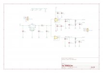
The approximate schematic is attached below. 22uf Wima mks4 film caps were used for opamp output capacitors without problems. There was no need for Vref dividers on the AVCC board so I left those out. They are on the dac board and I used 1k resistors instead of 10k to help reduce I/V stage input bias imbalance and the HD that can cause (mostly 2nd harmonic).
In this case the AVCC regulator includes an on-board LT1086-5 as a pre-regulator for a plug-in 3.3v LTC6655 reference module. The AD797 are mounted on a single Brown Dog dual opamp adapter so the socket can be wired for standard dual opamps. The top opamp also has a stick-on heat sink.
The AVCC board and opamp outputs are physically located as close to the ES9028PRO AVCC inputs as I could manage. That is in accordance with advice from ESS.
I measured input current to the Trident regulators at about 130ma each when they were driving the added 33-ohm loads. The loads draw 100ma, and the ADM7151 regulators probably draw a little, so I figured around 25-30ma range is what each of the AVCC opamps would have to supply.
ESS measured performance before for an earlier Sabre dac using AD797 and found lowest audio output THD with that opamp used for AVCC. I also used them before with good results, except they didn't like when I added film caps to the OPA1612 output stage +-15v power. Rather than fix the AD797 issue at that time I just replaced them with OPA1612 and left it at that since the dac at the time was an ES9038Q2M.
In this case the AVCC regulators have their own +-15v supply free of film caps. Eventually, I may see if AD797 can be made stable with film caps on the +-15v rails that I use for the output stage opamps.
The approximate schematic is attached below. 22uf Wima mks4 film caps were used for opamp output capacitors without problems. There was no need for Vref dividers on the AVCC board so I left those out. They are on the dac board and I used 1k resistors instead of 10k to help reduce I/V stage input bias imbalance and the HD that can cause (mostly 2nd harmonic).
In this case the AVCC regulator includes an on-board LT1086-5 as a pre-regulator for a plug-in 3.3v LTC6655 reference module. The AD797 are mounted on a single Brown Dog dual opamp adapter so the socket can be wired for standard dual opamps. The top opamp also has a stick-on heat sink.
The AVCC board and opamp outputs are physically located as close to the ES9028PRO AVCC inputs as I could manage. That is in accordance with advice from ESS.
Attachments
Last edited:
I am pretty sure all this experience and options you have already handy will enable to gain a lot of development time around the AKM or whatever DAC chip
Claude,
Nice to see you are still here. Thanks again for your summary of the German audio magazine dac reviews.
To some extent your guess about experience so far helping with future projects is probably correct. However, in the case of AVCC, I think we have probably reached the limit for simple opamp AVCC regulators without pass or shunt transistors. For ES9038PRO and AK4499, more current will be needed and other types of regulators topologies will have to be considered. Perhaps some time will be needed to find a preferred solution going forward.
I was wondering if anyone had any thoughts about this, could apply to 9028Pro or 9018 DACs aswell
I purchased a faulty HifiMeDIY 9038Pro DAC off a friend of mine for cheap, the problem causing no sound was very simple to fix, it uses a LT1054 chip to generate the negative supply rail for the op amps and somehow it got fried, after wiring in proper dual rail supply all works as intended.
Now this DAC has flaky reputation due to measurements posted on audiosciencereview.com, supposed to measure attoriciously in noise and distortion.
To be honest it sounded fine and compared to something like the ODAC I wouldnt think there is anything wrong with it, but for certain it did not perform like the excellent measuring, dual 9038Q2M Topping D50, with some slight wooliness and boominess in comparison.
I wanted to improve this DAC, first thing was addressing I/V stage, it uses OPA2134... can this even handle the output current of UDA38Pro?? I seen Mark mention in another thread the LME49720 cant handle the current of this DAC, and these are very similar
Anyway assuming this was contributing to mediocre sound quality I ended up discovering something unusual about this DAC when experimenting with the I/V stage.
If I listen to one of the differential outputs of DAC single-ended I can hear a constant low hiss/noise , like pink noise.
its same on both outputs for each channel, even taking output directly from the DAC in voltage mode so its not the I/V.
Seeing as this noise cancels after the unbalancing op amp amp I thought there is a slight chance this is normal, but the topping D50 is dead silent in comparison.
I then completely stripped the DAC down to try and fix this noise:disconnected the bulky Chinese TCXO,
bypassed DC-DC converters and fed low noise regulator.
the only thing in the DAC receiving power right now is the DAC chip and MCU, and yet the noise persists.
There were a few users on the Head-Fi forum who showed interest in modding this DAC and the Topping D50, I messaged a couple of them and one was kind of enough do a test for me. He checked one the differential outputs on his HifiMe and told me he heard the exact same thing.
Is there any explanation to whats happening here?
I havent tested if the problem is rooted in the power supplies after the DC-DC converters.
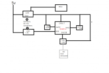
attached is a diagram of the layout.
a couple iffy things: one side DVCC receiving 3.6V and the other receiving 3.3v after a 2nd regulator shared with XO supply
These were the 2 reasons for removing the XO and bypassing the DC-DC converters.
But I cant see this power supply layout being so problematic as to cause audible hiss/noise, only degrading performance.
The DAC has plenty of decoupling caps including OSCONs at each regulator.
I purchased a faulty HifiMeDIY 9038Pro DAC off a friend of mine for cheap, the problem causing no sound was very simple to fix, it uses a LT1054 chip to generate the negative supply rail for the op amps and somehow it got fried, after wiring in proper dual rail supply all works as intended.
Now this DAC has flaky reputation due to measurements posted on audiosciencereview.com, supposed to measure attoriciously in noise and distortion.
To be honest it sounded fine and compared to something like the ODAC I wouldnt think there is anything wrong with it, but for certain it did not perform like the excellent measuring, dual 9038Q2M Topping D50, with some slight wooliness and boominess in comparison.
I wanted to improve this DAC, first thing was addressing I/V stage, it uses OPA2134... can this even handle the output current of UDA38Pro?? I seen Mark mention in another thread the LME49720 cant handle the current of this DAC, and these are very similar
Anyway assuming this was contributing to mediocre sound quality I ended up discovering something unusual about this DAC when experimenting with the I/V stage.
If I listen to one of the differential outputs of DAC single-ended I can hear a constant low hiss/noise , like pink noise.
its same on both outputs for each channel, even taking output directly from the DAC in voltage mode so its not the I/V.
Seeing as this noise cancels after the unbalancing op amp amp I thought there is a slight chance this is normal, but the topping D50 is dead silent in comparison.
I then completely stripped the DAC down to try and fix this noise:disconnected the bulky Chinese TCXO,
bypassed DC-DC converters and fed low noise regulator.
the only thing in the DAC receiving power right now is the DAC chip and MCU, and yet the noise persists.
There were a few users on the Head-Fi forum who showed interest in modding this DAC and the Topping D50, I messaged a couple of them and one was kind of enough do a test for me. He checked one the differential outputs on his HifiMe and told me he heard the exact same thing.
Is there any explanation to whats happening here?
I havent tested if the problem is rooted in the power supplies after the DC-DC converters.
attached is a diagram of the layout.
a couple iffy things: one side DVCC receiving 3.6V and the other receiving 3.3v after a 2nd regulator shared with XO supply
These were the 2 reasons for removing the XO and bypassing the DC-DC converters.
But I cant see this power supply layout being so problematic as to cause audible hiss/noise, only degrading performance.
The DAC has plenty of decoupling caps including OSCONs at each regulator.
Attachments
Last edited:
It is 5V linear supply (originally 5V came from the USB input), The LDOs could be identified as LP5907.
yes all LDOs are fed 3.6V, which powers the MCU directly.
I found datasheet for 9018 and 9038Q2M online, but no 9038Pro. I compared all power pins and they match the 9018 but there is no VCCA for the 9018 and couldnt find any visible power traces that might lead to it. The LDO for DVCC B looks like it only powers that pin and the XO, but this seems like the most likely so maybe the trace goes under the chip to the VCCA pin from behind (there are some N.C pins on the 9018 a few pins across DVCC B)?
Last edited:
Does AKM consider you as one of their trustfull beta tester")
No. The board is really for my friend, Jam, who is a successful high end audio designer working on a new product line. Not that he would or wouldn't offer a dac, but at least he has some influence with the local AKM distributor. They asked AKM to send a board, which it apparently has done. The board will come here first to get it up and running, and to see how it sounds compared to a reasonably good Sabre dac implementation (and Sabre is complicated enough to make sound good, IME).
either I2S from Amanero interface or optical SPDIF , selected with a switch.
It should have an auto-mute function which would disable the outputs in the absence of valid input. Maybe the the MCU is programmed to disable that dac function or something.
If you can attach to the I2C signals somewhere between the MCU and dac chip, you could use a $10 logic analyzer to read out how the MCU is configuring the dac registers. USB Logic Analyzer Device Set Compatible to Saleae 8CH 24MHz For ARM FPGA 8937635044623 | eBay
- Home
- Source & Line
- Digital Line Level
- ES9038Q2M Board