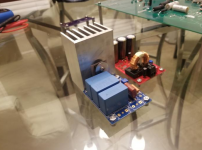
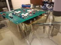
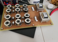
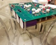
Got the heatsink for the Maida tapped and drilled and got the standoffs figured out for the DAC and filter board.
The 9-pin connectors will be as close as possible to minimize that distance, then the XLR outputs will be right next to the filter outs.
I also added two standoffs/holes to the filter near the output transformers because they are heavy and to combat the flex. Since there is no solder mask, I put some paint and electrical tape around the holes so the standoffs don't touch the ground pour.
Attachments
Noise floor and things to take care of
Hallo,
I had very little time in the last few month but I’m now ready to (finally!) begin building the dac. I’m therefore re-reading all documentation and the thread.
Concerning noise floor, as measured by Marcel recently: how that can be improved? Low noise regulation? B+ regulation? Do good E88cc make a difference?
I’m asking just to better understand where to put my attention since I’ve not started yet.
Thanks,
Mirko
I can't say that any of it is necessary, but since this is an expensive project anyway, I went all-out and tried to minimize any noise, usually overpaying for over-spec'd parts just for my own satisfaction lol. Nothing crazy, Vishay RN/CMF resistors, WIMA, Kemet, etc. Every resistor is at least 1%, then the ones that are specified in the schematic to be 1%, I used 0.1%.
I'm using external PSUs for the -300V, the 6.3V, and a 5V for my USB thing. I'm also using this reg for the on-board 5V supply.
My case layout is also really geared towards separating power things from signal, and the signal ground connects to the chassis at one point using this circuit.
Hopefully the efforts aren't wasted. I won't have any way to measure the noise, so hopefully I just don't hear it.
There are a couple of resistors that should be stable and shouldn't have too much 1/f noise, particularly the anode resistors and anode trimming potmeters (RV1 and RV2). I recommend using metal film for the resistors and cermet for the trimming potmeters.
E88CC valves with good matching between their halves could very well lead to a lower noise floor than E88CC valves with somewhat worse matching. If you can measure or record the noise, you could try various permutations of the E88CCs, trim the anode trimming potmeters every time and see if it makes any difference. I used old old stock E88CC's in random order, by the way.
Retrimming the anode trimming potmeters RV1 and RV2 every now and then definitely helps.
Crosstalk from the sigma-delta modulate to the voltage reference or to the clock that drives the lower E88CCs worsens the noise floor, but I don't know any way to reduce that further than it is already reduced. Reducing this crosstalk was the reason to go for a four-layer board with the analogue/mixed signal circuitry on the top, the digital stuff on the bottom and two planes in between. C5, C24, C25 and C34 are also there specifically to keep the crosstalk to a minimum.
For the raw DSD version, you could try different DSD rates and using the bit clock or the master clock.
Last edited:
I bought the WaveIO, which has data, word clock, bit clock, master clock, Vin, and 5 GNDs. I think to connect to P9, it's:
data to pin 5
word clock to pin 11
bit clock to pin 9
master clock to nothing
Vin to pin 19 or 20
GND to pins 2, 4, 6, 8, 10?
data to pin 5
word clock to pin 11
bit clock to pin 9
master clock to nothing
Vin to pin 19 or 20
GND to pins 2, 4, 6, 8, 10?
There are a couple of resistors that should be stable and shouldn't have too much 1/f noise, particularly the anode resistors and anode trimming potmeters (RV1 and RV2). I recommend using metal film for the resistors and cermet for the trimming potmeters.
May be a waste of $$, but I have used Vishay Foil 1240W series trimpots in my build, simply because of their position at the anode and because they are less likely to wander than the cemets.
Thanks Marcel, acg, SonnyMarrow for the hints, already processed as per your suggestions 🙂
I don't seem to find a BOM for the B3 Lundahl filrters, apart from transformers and RM8 inductors suggested by Ray. Does anybody have the BOM handy?
Many thanks in advance for the support!
Mirko
I don't seem to find a BOM for the B3 Lundahl filrters, apart from transformers and RM8 inductors suggested by Ray. Does anybody have the BOM handy?
Many thanks in advance for the support!
Mirko
Re: trimpots - they need to be trimmable from above, otherwise this will be a PITA.
One turn trimmers for the tube balancing seem to me optimal in this position. With a multiturn trimmer it will not be easy to sweep, and sweeping gets you there!
One turn trimmers for the tube balancing seem to me optimal in this position. With a multiturn trimmer it will not be easy to sweep, and sweeping gets you there!
May be a waste of $$, but I have used Vishay Foil 1240W series trimpots in my build, simply because of their position at the anode and because they are less likely to wander than the cemets.
I see Vishay 1240W are 1/4W, enough for what they have to dissipate?
Ciao,
Mirko
See post #637, https://www.diyaudio.com/forums/dig...-linear-audio-volume-13-a-64.html#post6310765 The data line is not likely to get disconnected in the original valve DAC, but the data line will presumably be at a constant level when the ECC81 crystal oscillator hasn't started up yet, so the effect is the same.
The calculation in post #637 is worst case, relates to a situation that happens temporarily during start-up and those Vishay 1240W trimming potmeters are milspec components that are very conservatively rated, so chances are they will work just fine in practice, but formally 0.25 W is a bit tight.
Thanks for explanation Marcel, pretty clear. In the end I took the Bourns. I had to split the bom between Mouser and DigiKey but now I should be ready to go 🙂
Ciao,
Mirko
Ciao,
Mirko
It’s me, once again. At least, my spamming activity shows that I’m committed on the project 🙂
Still struggling a bit to find the right specs for the filter components but I’ll sort it out.
Moving toward supply... feel free to insult me for what I’m about to ask
Has anybody ever tried to use a switching power supply instead of a main transformer?
We’re all pushing on the various low noise regulations so, for example, what’s the point in not using a -320 from a switching supply and then regulate it precisely with a hv reg like Maida or Didden’s? This way any magnetic field is kept away from tubes and other sensitive stage and we achieve a lot of space saving.
I found such a module on AliExpress, up to 520V, a couple low voltage lines, conceived for a tube amp use. I know it is probably crap but the real question is: if I handle all supply lines with post regulation, do I really care about noise and shape of what’s produced by a smps?
Ciao,
Mirko
Last edited:
It should work if you manage to shield + filter and/or regulate everything well enough. It will be more difficult than for a valve amplifier, though, as the valve DAC is by design more sensitive to far ultrasonic interference than an amplifier.
Sigma-delta DACs such as the valve DAC (both the original and the DSD version) multiply a sigma-delta modulate with their reference voltage or current. Because of the way sigma-delta modulators work, a sigma-delta modulate always has strong out-of-band quantization noise. Far ultrasonic ripple on the voltage or current reference can frequency-convert some of that out-of-band quantization noise into the audio band, in much the same way as the mixer stage in a receiver frequency-converts the RF signal to the IF band. A similar though somewhat more complicated story applies when the clock gets phase modulated by far ultrasonic ripple.
So all in all, when you don't shield and filter and/or regulate your SMPS well enough, you will get an increase in the noise floor at audio frequencies. If you do shield and filter and/or regulate it well enough, then it should work fine. You will have to determine by experimentation whether it is good enough.
It's good to see a few builds of both versions of Marcel's DAC underway here and hopefully some will soon be delivering music.
But, there are quite a few other 'DSD' boards 'out there' after the GB and I'm wondering how those builds are progressing?
But, there are quite a few other 'DSD' boards 'out there' after the GB and I'm wondering how those builds are progressing?
I successfully programmed the LX45! Used the Impact software and loaded the new .mcs file, made sure I selected the correct memory manufacturer and model number, and it reported the flashing as successful. Can't test it until I get the rest of the parts in.
Well, I bought myself a new JTAG programming cable only to find out it resulted in the exact same error message as the old cable. In the end it turned out to be related either to an old iMPACT project file referring to the wrong FPGA type, or to a wrong DIP switch setting on the FPGA board, or both.
Anyway, if anyone wants to buy a second-hand programming cable that has only been used once for 20 euros, please let me know.
When I finally managed to program the module, the integrator clipping issue turned out to be much improved but not solved, so I had to make some further changes. The attachment is an update of the TE0630 LX45 configuration file with these changes:
1. Last integrator's linear range doubled by giving it one bit extra
2. Sigma-delta modulator's input scaling factors slightly reduced
3. Bit clock for the output side of the SRC4392 generated in a cleaner way
4. Functionality of DIP switch S1C changed: when it is on, the neon lamps also indicate the sigma-delta mode and filter type when the surprise button is not pressed
The attached figure shows the filter chain. It's the exact same as 8 days ago, but I hadn't shown it yet.
Attachments

I successfully programmed the LX45! Used the Impact software and loaded the new .mcs file, made sure I selected the correct memory manufacturer and model number, and it reported the flashing as successful. Can't test it until I get the rest of the parts in.
Damn, I posted my update three minutes too late... 😉
- Home
- Source & Line
- Digital Line Level
- Valve DAC from Linear Audio volume 13