A S/PDIF switch can be useful when we have more digital audio sources than the number of inputs available on a DAC.
I wanted to do this a long while ago and finally managed to get at it recently.
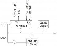
This little project makes use of the internal 8-channel selector offered by WM8805 S/PDIF receiver, and was designed to select one out of up to 8 S/PDIF feeds under the monitor and control of an Arduino Nano micro controller board.
Unlike a usual switch-and-buffer type of device, WM8805 re-clocks its on-chip S/PDIF transmitter and does not pass the incoming jitter on to the output, therefore upkeeps the S/PDIF signal quality in terms of jitter reduction/rejection. That is why so my choice was.
Whazon’s operation is simple, it keeps polling the 8 inputs in turn and stops at the first one its PLL manages to lock up to. A duplicated, de-jittered S/PDIF signal is then sent out with the S/PDIF transmitter, available in coaxial and optical form.
Whatzon receives remote control via an inexpensive Bluetooth-serial I/O tranceiver, model HC-05, paired with a smart phone running a Bluetooth terminal app.
The channel polling described above can be enabled/disabled with the phone. Forced channel change to desired channel, and next higher channel are also easily implemented.
An I2S copy of the selected input signal is also sent out at WM8805’s bidirectional digital audio interface for future project expansion. It is however not being put to use at present, except that a buffered copy of the LRCK is sent to the Arduino for exact sample rate detection (that WM8805 is not fully capable of).
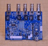
The PCB is a compact 10cm * 10cm double sided design, with a break-away optical I/O section. Whazon accepts 4 coaxial (BNC) and 4 optical inputs with current PCB design. It is possible to replace the optical input receivers in the current breakaway design with BNC connectors to make all channels BNC input. The coupling and termination circuit layout around the WM8805 works with both types for that 4 channels.
Whazon is powered by a 5Vdc cell phone charger through a micro USB port that serves as a programming port for the Arduino as well when connected to a PC that runs Arduino development system.
Successful so far: input channel polling, PLL locking, exact sample rate detection -- tested good with 44.1, 48, 88.2, and 96KHz signals, haven't tested 32KHz, 176.4KHz, and 192KHz yet as I don't have such sources.
Being worked on: an OLED screen display that shows current input channel and sample rate --- Done.
In the plan: A button push or a remote that forces switching to the next input and starting the polling/channel rotation --- Remote done.
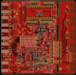
The PCB layout screen shot is of top side of Rev.2 design to be sent to a PCB house soon.
There is a youtube video in post #5 below that shows this project in action.
I wanted to do this a long while ago and finally managed to get at it recently.
This little project makes use of the internal 8-channel selector offered by WM8805 S/PDIF receiver, and was designed to select one out of up to 8 S/PDIF feeds under the monitor and control of an Arduino Nano micro controller board.
Unlike a usual switch-and-buffer type of device, WM8805 re-clocks its on-chip S/PDIF transmitter and does not pass the incoming jitter on to the output, therefore upkeeps the S/PDIF signal quality in terms of jitter reduction/rejection. That is why so my choice was.
Whazon’s operation is simple, it keeps polling the 8 inputs in turn and stops at the first one its PLL manages to lock up to. A duplicated, de-jittered S/PDIF signal is then sent out with the S/PDIF transmitter, available in coaxial and optical form.
Whatzon receives remote control via an inexpensive Bluetooth-serial I/O tranceiver, model HC-05, paired with a smart phone running a Bluetooth terminal app.
The channel polling described above can be enabled/disabled with the phone. Forced channel change to desired channel, and next higher channel are also easily implemented.
An I2S copy of the selected input signal is also sent out at WM8805’s bidirectional digital audio interface for future project expansion. It is however not being put to use at present, except that a buffered copy of the LRCK is sent to the Arduino for exact sample rate detection (that WM8805 is not fully capable of).
The PCB is a compact 10cm * 10cm double sided design, with a break-away optical I/O section. Whazon accepts 4 coaxial (BNC) and 4 optical inputs with current PCB design. It is possible to replace the optical input receivers in the current breakaway design with BNC connectors to make all channels BNC input. The coupling and termination circuit layout around the WM8805 works with both types for that 4 channels.
Whazon is powered by a 5Vdc cell phone charger through a micro USB port that serves as a programming port for the Arduino as well when connected to a PC that runs Arduino development system.
Successful so far: input channel polling, PLL locking, exact sample rate detection -- tested good with 44.1, 48, 88.2, and 96KHz signals, haven't tested 32KHz, 176.4KHz, and 192KHz yet as I don't have such sources.
Being worked on: an OLED screen display that shows current input channel and sample rate --- Done.
In the plan: A button push or a remote that forces switching to the next input and starting the polling/channel rotation --- Remote done.
The PCB layout screen shot is of top side of Rev.2 design to be sent to a PCB house soon.
There is a youtube video in post #5 below that shows this project in action.
Attachments
Last edited:
While your project has more capabilities, there is a much simpler way to make an SPDIF switch.
SPDIF is basically the same bandwidth and electrical parameters and NTSC analog video. 1volt into 75ohms 6mhz.
So any plain old analog video switch will work. Maxim makes many video crosspoint chips with built in cable drivers. TI does a s well. With a MAX453 you can make an 8x1 switch with just 1 IC and a few resistors. No need for transformer coupling. Most of these switch IC's are DC coupled although AC coupling would work just fine as well.
If using an OEM professional video switch you just need to be sure it doesn't have sync tip clamping enabled if so equipped. As we know SPDIF does not have a sync pulse and the clamp may chew up the data stream
I agree that there can be many and simple ways of switching SPDIF feeds. Whazon is perhaps more of a SPDIF receiver than a mere switch. An I2S interface makes it possible to hook up with other DIY projects in the forum that also come with I2S I/O, an OLED display makes it a toy of a little more fun. A bit of automation and remote control make it an practicable device in a stereo equipment rack too -- living room worthy was one of the objectives. Coupling transformers may help cut down ground loops loops among but can always be opted out when not needed.
The OLED display is up and running")
Channel polling in action
All Channels Down
Channel 4 has something
CH4 is good
Channel polling in action
All Channels Down
Channel 4 has something
CH4 is good
Whazon made living room worthy
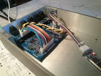
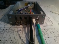
I finally managed the most tedious part of the project, making an enclosure. Now it's in the system and doing its deed.
In Action Video
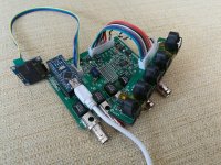
A few pictures inside and back.
Remote control is via a Bluetooth serial tranceiver module HC-05 paird with a smartphone running a Bluetooth Terminal app.
I finally managed the most tedious part of the project, making an enclosure. Now it's in the system and doing its deed.
In Action Video
A few pictures inside and back.
Remote control is via a Bluetooth serial tranceiver module HC-05 paird with a smartphone running a Bluetooth Terminal app.
Attachments
In my searches for a source switch I realized I would like to switch signals as early as possible to avoid analog degradation. This meant switching in the digital domain, and the common denominator for digital audio is S/PDIF. It is easy to find HDMI audio extractors that have S/PDIF outputs these days, and most devices are configurable for PCM output. I couldn't find any acceptable designs or products, besides nattawa's design, that focuses around high quality switching/jitter cleaning of S/PDIF signals. The WM8805 is really a great chip and this design recognizes all available, realistic sampling rates. Nattawa's microcontroller code intelligently handles the quirks of the WM8805, allowing perfect software control over the switching and sample rates. I've modified the design a bit to simplify the architecture and created my own version of his design that works excellently.


If you have multiple digital sources and need a way to switch between them, I highly recommend this project.
If you have multiple digital sources and need a way to switch between them, I highly recommend this project.
Last edited:
I finally managed the most tedious part of the project, making an enclosure. Now it's in the system and doing its deed.
In Action Video
A few pictures inside and back.
Remote control is via a Bluetooth serial tranceiver module HC-05 paird with a smartphone running a Bluetooth Terminal app.
Hello nattawa, is it possible to share schematics, pcb files and arduino sketch? I am in process of designing preamp with dac and would like to have switch for digital imputs.
Hi gemby, yes, I'm more than happy to share the design. I'll make ready a file package and come back to you in a couple days.
Tnx, i appreciate it ;-)
Update. Project Release at Rev.3 PCB Layout.
Ready to share PCB fabrication data and build information. Interested please enquire by PM for the file package. It is too big to post as an attachment.
Rev.3 has got Flat Flexible Cables replacing the wire harness for I2S interface and the wiring going between the main PCB and the Toslink PCB. It accommodates more options of coaxial connectors. It has got 4 mounting holes as well for easy mounting to an enclosure, unlike previous revisions that are mounted to a rear panel by BNC connectors.

The layout is two piece in one, the main PCB and the Toslink PCB. Need to separate and then assemble individually. Picture shows how they would be put together inside an enclosure.

I have a readme file that is too big to attach. Below is part of that readme that describes about the PCB.
3. PCB Description
3.1 photo with notes about the headers

3.2 Power Inlet Options/Scenarios:
3.2.1 The microUSB jack on the Toslink PCB is the power inlet. An old cell phone charger that puts out 5V/0.5A will power a Whazon well. The +5V powers the Toslink PCB itself and, through the FFC (Flexible Flat Cable) connection, powers the main PCB as well.
3.2.2 The 2-pin header on the main PCB is an alternative +5V power inlet in case the Toslink PCB is not used.
3.2.3 The mini USB jack on the Arduino module can serve as a power inlet as well. When connected to a host computer (while compiling and uploading the codes), the +5V from the USB port of the computer supplies Arduino Nano which in turn puts out 4.7V with enough current capacity to power the rest of Whazon. This is quite convenient at system bringing up or working on the code -- no need to hook up a separate power supply.
3.3 FFC Connectors/cables
3.3.1 A 20-way FFC connects the main PCB and the Toslink I/O PCB
3.3.2 Prepared for project expansion, a 10-way FFC connects the WM8805's I2S interface to an external device (DAC for example)
3.4 Coaxial RX/TX:
3.4.1 The coaxial input/output connectors are all isolated in PCB design, from the common reference (GND) and from each other, to prevent formation of ground loops within inter-connected equipment.
3.4.2 The outer conductor of the connectors, however, is coupled with a 1nF capacitor to a common piece of wire, that can be in turn tied to the metalwork of the enclosure to fend off RF interference.
3.4.3 Options in hardware: The layout design accommodates several types of coaxial connector: an end launch BNC, an end launch SMB, an upright SMB, a right-angle SMB, or a U.FL-R connector.
3.5 Accessing the Arduino from Outside an Enclosure: The microUSB jack for power can also serve as the Arduino programming port. A home-made 4-wire adapter is needed to bridge the 4-pin header on the Toslink PCB and the miniUSB jack on the Arduino Nano module.
3.6 Surface Mount parts.
3.6.1 Smallest 2-pin component is in 0805 package, small yet still easy to handle.
3.6.2 Hand-soldering Friendly: Unlike most SMD projects seen in our forums, that simply take ready-made IPC7351 compliant land patterns, I customized the land patterns so that all components have sufficient pad exposure making them easy to access by a tip of a soldering iron.
Control with a smartphone. User can name the buttons. Controls include direct channel select, next higher channel, toggle enable/disable polling. Upper part of the screen is the talkback from the Whazon.

Schematic.
View attachment WHAZON_3-Sch.pdf
Ready to share PCB fabrication data and build information. Interested please enquire by PM for the file package. It is too big to post as an attachment.
Rev.3 has got Flat Flexible Cables replacing the wire harness for I2S interface and the wiring going between the main PCB and the Toslink PCB. It accommodates more options of coaxial connectors. It has got 4 mounting holes as well for easy mounting to an enclosure, unlike previous revisions that are mounted to a rear panel by BNC connectors.
The layout is two piece in one, the main PCB and the Toslink PCB. Need to separate and then assemble individually. Picture shows how they would be put together inside an enclosure.
I have a readme file that is too big to attach. Below is part of that readme that describes about the PCB.
3. PCB Description
3.1 photo with notes about the headers
3.2 Power Inlet Options/Scenarios:
3.2.1 The microUSB jack on the Toslink PCB is the power inlet. An old cell phone charger that puts out 5V/0.5A will power a Whazon well. The +5V powers the Toslink PCB itself and, through the FFC (Flexible Flat Cable) connection, powers the main PCB as well.
3.2.2 The 2-pin header on the main PCB is an alternative +5V power inlet in case the Toslink PCB is not used.
3.2.3 The mini USB jack on the Arduino module can serve as a power inlet as well. When connected to a host computer (while compiling and uploading the codes), the +5V from the USB port of the computer supplies Arduino Nano which in turn puts out 4.7V with enough current capacity to power the rest of Whazon. This is quite convenient at system bringing up or working on the code -- no need to hook up a separate power supply.
3.3 FFC Connectors/cables
3.3.1 A 20-way FFC connects the main PCB and the Toslink I/O PCB
3.3.2 Prepared for project expansion, a 10-way FFC connects the WM8805's I2S interface to an external device (DAC for example)
3.4 Coaxial RX/TX:
3.4.1 The coaxial input/output connectors are all isolated in PCB design, from the common reference (GND) and from each other, to prevent formation of ground loops within inter-connected equipment.
3.4.2 The outer conductor of the connectors, however, is coupled with a 1nF capacitor to a common piece of wire, that can be in turn tied to the metalwork of the enclosure to fend off RF interference.
3.4.3 Options in hardware: The layout design accommodates several types of coaxial connector: an end launch BNC, an end launch SMB, an upright SMB, a right-angle SMB, or a U.FL-R connector.
3.5 Accessing the Arduino from Outside an Enclosure: The microUSB jack for power can also serve as the Arduino programming port. A home-made 4-wire adapter is needed to bridge the 4-pin header on the Toslink PCB and the miniUSB jack on the Arduino Nano module.
3.6 Surface Mount parts.
3.6.1 Smallest 2-pin component is in 0805 package, small yet still easy to handle.
3.6.2 Hand-soldering Friendly: Unlike most SMD projects seen in our forums, that simply take ready-made IPC7351 compliant land patterns, I customized the land patterns so that all components have sufficient pad exposure making them easy to access by a tip of a soldering iron.
Control with a smartphone. User can name the buttons. Controls include direct channel select, next higher channel, toggle enable/disable polling. Upper part of the screen is the talkback from the Whazon.
Schematic.
View attachment WHAZON_3-Sch.pdf
minor update
Fellow member danielutzu brought the rear panel design to my attention. I guess a hole pattern drawing will be helpful for those who would put the project into an enclosure. The attached shows the hole pattern. A dxf file of that drawing was added to the file package as well.

Another update is about the Arduino sketch. A screen saver feature was added to help prolong the service life of an OLED display screen.
My own Whazon unit has been in service for a few years now, and I noticed the OLED screen has developed image retention, or burn-in, despite the brightness setting has been quite low (but sufficiently bright even in a bright living room). The screen saver reduces the OLED display service duty by about 90% when the unit has come into a static condition for 15 minutes, supposedly doing the pixels in the screen a big favor by reducing wear and tear.
I also tried a larger, 2.42" OLED display module, and it is a lot more legible from a distance than is a 1.5" screen. The Whazon Arduino sketch has now been made ready to support that 2.42" screen.
Fellow member danielutzu brought the rear panel design to my attention. I guess a hole pattern drawing will be helpful for those who would put the project into an enclosure. The attached shows the hole pattern. A dxf file of that drawing was added to the file package as well.
Another update is about the Arduino sketch. A screen saver feature was added to help prolong the service life of an OLED display screen.
My own Whazon unit has been in service for a few years now, and I noticed the OLED screen has developed image retention, or burn-in, despite the brightness setting has been quite low (but sufficiently bright even in a bright living room). The screen saver reduces the OLED display service duty by about 90% when the unit has come into a static condition for 15 minutes, supposedly doing the pixels in the screen a big favor by reducing wear and tear.
I also tried a larger, 2.42" OLED display module, and it is a lot more legible from a distance than is a 1.5" screen. The Whazon Arduino sketch has now been made ready to support that 2.42" screen.
Sure. Will send you pm on Monday.Hi, I’m in need of a project such as yours
for those who wonder how Whazon would work with a DIY DAC board, I have an example. Attached picture is of Whazon working with my ASRC-DAC project based on AK4137 and AK4493, with backend master clock si570, all under the control of an Arduino Nano sitting on the Whazon. That ASRC-DAC project was documented here in 2018.

I built that DAC project in 2019-2020, then the fire at AKM halted it, and broke my heart too. Thankfully they did not give up, AK4493 is back, (this time AK4493S).
This DAC has sit in my living room system for a couple months now performing to satisfaction, less a hole in the front panel waiting for a panel light on order yet to arrive.
Hi Shaoyi,
first of all, thank you so much for your kindness in sharing your effort, I'm about to pull the trigger on this one and thought I'd just ask you a couple of questions:
1 - Can I safely ignore all "DNI" entries in the BOM?
2 - 47uH inductors, L1 to L5, I can't find them in the circuit design, are these also DNI/Optional?
3 - R32 - R33RX4ISO%5SMT,33R, I can't figure out which part number this is...it seems like a 4 way 44Ohm resistor...but can you give me a bit of help in finding the right PN?
4 - C7 - C10, they're supposedly capacitors, but you've stated their value as 0R....looking on the picture you shared these look like resistors?
5 - T6 - T10, same as inductors mentioned above in #2, are these the optional transformers you mentioned in the README?
Thanks in advance!
1 - Can I safely ignore all "DNI" entries in the BOM? -- yes, you can ignore all DNI components.
2 - 47uH inductors, L1 to L5, I can't find them in the circuit design, are these also DNI/Optional? -- these are sitting by the optical input/output modules, U2-U6 on their 3.3V supply. By the way, if you have trouble sourcing what's in the BOM for these inductors, you can substitute with 1206 or 0805 size ferrite beads, such as PE-0805FB601ST.
3 - R32 - R33RX4ISO%5SMT,33R, I can't figure out which part number this is...it seems like a 4 way 44Ohm resistor...but can you give me a bit of help in finding the right PN? -- that was a mistake on my part...sorry. You're right about it being a 4-way resistor array, it's Rohm MNR14E0APJ330, or any 4-way 33-ohm resistor array that size.
4 - C7 - C10, they're supposedly capacitors, but you've stated their value as 0R....looking on the picture you shared these look like resistors? --when using optical input modules for that four channels C7-C10 need to be shorted to allow CMOS level signal direct coupling, therefore 0R resistors in place of C7-C10.
5 - T6 - T10, same as inductors mentioned above in #2, are these the optional transformers you mentioned in the README? --Yes. they are co-siting alternatives to T1-T5. you can use Murata transformer DA101C, SMD type or through-hole variety, or cheaper PE65612 from ebay
- Home
- Source & Line
- Digital Line Level
- Whazon, a S/PDIF switch built around WM8805