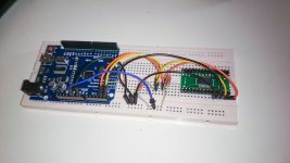
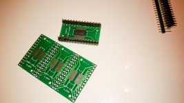
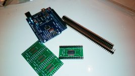
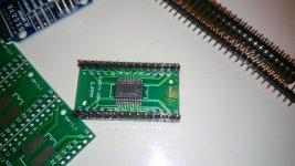
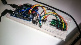
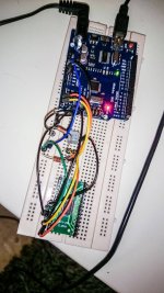
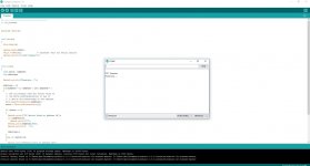
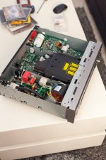
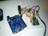
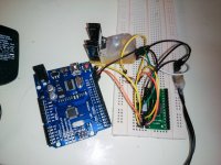
pcm1796 i2c arduino uno wiring configuration ? Hello friends I try unsuccessfully to reprogram the PCM1796 In I2C the datasheet is Very confusing for a dac output stage that i Going to design . 1) What a way to wiring from the PCM1796 To the arduino uno ? 2) Voltage supply 5V ? or 3.3V ? I am sure that wiring correct Because of that I2C scanner that scans the I2C-bus for devices is Not detects the PCM1796
Attachments
-
 16602114_3522005172094_5857989485469763520_o.jpg190.9 KB · Views: 279
 -
 Capture.JPG 1.JPG193.4 KB · Views: 85
 -
 Capture.JPG56 KB · Views: 110
 -
 16707244_3522005772109_3732492120665447037_o.jpg227.6 KB · Views: 264
 -
 16700240_3522005892112_1153370733736117214_o.jpg170.3 KB · Views: 256
 -
 16665176_3522007292147_7911516872930057557_o.jpg253.8 KB · Views: 268
 -
 16602229_3522006532128_2123481828533024856_o.jpg218.5 KB · Views: 273
Last edited:
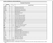
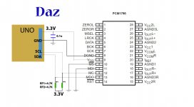
I haven't worked with the PCM1796 IC by myself but I studied its datasheet some time ago when planned my future DAC project. From what I learned you should supply 3.3VDC to the PCM1796 VDD pin. Digital inputs are TTL compatible and will be fine with 5V logic (arduino uno). Connection is rather simple. I2C is a 3 wire system. Just connect SCL/SDA pins of the arduino to the PCM1796 according to the specification that you attached and connect their GNDs together. Select the I2C slave address using two bits provided by the ADDR0 and ADDR1 pins. Look in the datasheet which number it makes with the rest of the address bits to tell arduino where to send the data.
You also need to put a small decoupling capacitor across the VDD and the adjacent DGND pins for stable operation (as close as you can to the PCM1796). If you want to actually see the output you need to implement the analog section as well and supply it with 5VDC.
Regards,
Oleg
You also need to put a small decoupling capacitor across the VDD and the adjacent DGND pins for stable operation (as close as you can to the PCM1796). If you want to actually see the output you need to implement the analog section as well and supply it with 5VDC.
Regards,
Oleg
First thanks for the reply OlegSh
so
from te uno
SCL to pin 12 (MC)
SDA to pin 13 (MDO)
What about Resistors the pull up resistor ?
3.3V to the pin 9 vdd digital power supply
ADDR0 ADDR1
Do both need to connect to the UNO?
( I need to connect them to the ground)
so
from te uno
SCL to pin 12 (MC)
SDA to pin 13 (MDO)
What about Resistors the pull up resistor ?
3.3V to the pin 9 vdd digital power supply
ADDR0 ADDR1
Do both need to connect to the UNO?
( I need to connect them to the ground)
Last edited:
Pull up resistors on the I2C lines are mandatory. Use something like 5k~10k for short wire runs (low cable capacitance). For long runs use smaller values but not too small not to overload the IC.
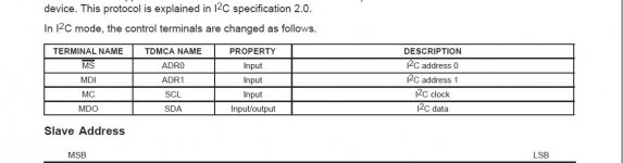
ADDR0 and ADDR1 should be connected either to DGND or to VDD to set them to "0" or "1", correspondingly (see page 21 of the datasheet "Slave Address" for details). This allows up to 4 different addresses to be selected.
ADDR0 and ADDR1 should be connected either to DGND or to VDD to set them to "0" or "1", correspondingly (see page 21 of the datasheet "Slave Address" for details). This allows up to 4 different addresses to be selected.
Pull up resistors on the I2C lines are mandatory. Use something like 5k~10k for short wire runs (low cable capacitance). For long runs use smaller values but not too small not to overload the IC.
ADDR0 and ADDR1 should be connected either to DGND or to VDD to set them to "0" or "1", correspondingly (see page 21 of the datasheet "Slave Address" for details). This allows up to 4 different addresses to be selected.
Like this ?
Attachments
")
BTW, why did you decide to use PCM1796 instead of PCM1794? The later allows much simpler hardware control. It does not have all the features available via I2C in PCM1796 but do you really need all of them? I plan to use PCM1794 in hardware mode in my next project even though I'm very much familiar with the arduino.

BTW, why did you decide to use PCM1796 instead of PCM1794? The later allows much simpler hardware control. It does not have all the features available via I2C in PCM1796 but do you really need all of them? I plan to use PCM1794 in hardware mode in my next project even though I'm very much familiar with the arduino.
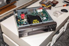
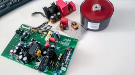
I still have some of pcm1796 from past my projects over the denon 3910
Attachments
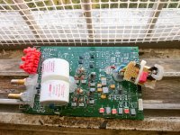
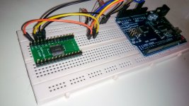
Assuming that you connected everything right I do not see a reason why it would not respond.
One possible problem is that the 0.1uF capacitor is too far from the IC to do anything. It should be next to the IC pins... Also did you connect RST pin to VDD? With this pin floating the IC will not start.
One possible problem is that the 0.1uF capacitor is too far from the IC to do anything. It should be next to the IC pins... Also did you connect RST pin to VDD? With this pin floating the IC will not start.
If I am not mistaken you should treat the R/W bit as part of the address. In this case if you intend to write to the PCM1796 you should look for addresses in the range from 0 to 255. The address you select by connecting ADDR0 and ADDR1 to DGND is 152(0x10011000) (LSB is set to 0 (write)).
Last edited:
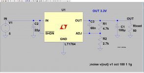
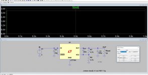
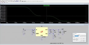
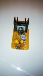
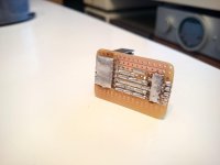
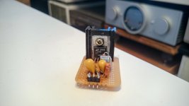
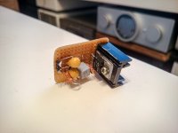
I built now
Voltage Regulators 3.3V
From the LT1764
I will try with him
to drive the VDD voltage to the PCM1796
Voltage Regulators 3.3V
From the LT1764
I will try with him
to drive the VDD voltage to the PCM1796
Attachments
-
 LT1764.JPG116.4 KB · Views: 63
 -
 LT1764 3.3V.JPG157.8 KB · Views: 50
 -
 LT1764 3.3V NOISE.JPG183.9 KB · Views: 56
 -
 16640831_3522338380424_4095511525926681491_n.jpg37.4 KB · Views: 41
 -
 16587203_3522338260421_232117304045788889_o.jpg116.7 KB · Views: 48
 -
 16586922_3522337900412_1417948756407075229_o.jpg144.4 KB · Views: 56
 -
 16487650_3522338740433_7418204335400980662_o.jpg261.9 KB · Views: 131
For some reason Does not work I built Voltage 3.3V From LT1764 It works well. Voltage 3.31 V ( output reg load resistor 100 ohm -ground to out ) But when I connect it to the PCM1796 VDD voltage falls to about 1 V I tried without the UNO And the same thing. I tried as well as connect the MBEL to ground - And the same thing. Something makes in the circuit voltage (vdd) to fall to about 1 V In addition, I tried to add a load resistor from the ground to out on thr LT1764 And the same thing. vdd= 1v
Attachments
Last edited:
- Status
- This old topic is closed. If you want to reopen this topic, contact a moderator using the "Report Post" button.
- Home
- Source & Line
- Digital Line Level
- pcm1796 i2c arduino uno wiring configuration