Hi,
I recently bought two adau1701 from sure. I do have some problems that I have not seen in the forum yet:
I use the ICP1 programmer (but also have the Cypress board with the Sure adapter).
Drivers seem to be installed OK, I get a green from SigmaStudio. I can read and write the eeprom, but do not seem to be able to communicate with the DSP directly. I get a comms failure and also cannot read the DSP registers. Both boards show the same behavior.
The most recent boards are a bit different. First they connect 5v power (pin2) on the 6 pin program connector instead of selfboot. I did check that the switch actually pulls selfboot on the 1701 to GND or 3.3V.
WP and Selfboot seem to be connected, where does WP go ?
Second the ICP1 also has a switch labled 'remote' and 'program' . Not sure what it does, no docs about this. Does anybody know more about the ICP1. It also has the Cypress EZUsb, a 16bit PIC processor on the board and another EEPROM. There is also some space for a Bluetooth module.
The 3 LED's are labled RUN, TX, RX. In one switch position (run) just the run is on. In the other (program) all three fade from dark to brighter and back etc.
Has anyone had success in communicating with the DSP via the ICP1 ?
Any suggestions how to debug this problem. I already spend way too much time with it.
Thanks!
Did you ever come across a solution for the "comms failed" error?
Thanks!
Did you ever come across a solution for the "comms failed" error?
Thanks!
I have mine working, ICP1 with the led's flashing, IIRC I cut the 5V feed from the ICP1 as was causing problems with the way I wanted to use the DSP boards - they are boxed up so not easy to get access to.
Setup as above I have to power and connect in the right order or it will go belly up, sometimes needing to go into device manager on the pc to remove unrecognised usbi?
Method I use that works:
1 Boot PC and load SigmaStudio
2 Plug USB cable from PC to ICP1 and check green lights flashing
3 Check for 'green' status in SigmaStudio hardware config tab (ADAU1701 -ICP1)
4 Power on the SureDSP
5 Connect ICP1 to SureDSP
6 Check SigmaStudio is still 'green' in hardware config tab (ADAU1701 -ICP1)
Should be good to go.
To make the SureDsp selfboot after loading a new design simply disconnect the cable between ICP1 and SureDSP and power off then back on the SureDSP.
Steps 4 and 5 are crucial for this to work, also the SureDSP should not be connected to the ICP1 when the ICP1 gets connected to the PC.
I had to scratch my head for a while before I got it sorted, but well worth it, great little boards.
Thank you so much, that seems to have gotten it working, along with some other tips I've seen from around, I used a laptop, my pc doesn't seem to play nicely, and powered the dsp board from a separate power only usb charger, it wouldn't work off the same laptop.
Hi all,
I seem to be the latest victim of the "Comms Failure". I spoke to Tim above and he mentioned that there seems to be no one solution to this. Lots of people report the Sure boards to be fussy.
I have both Sure/Wondom units in "1" switch position. I run sigma studio, plug in the ICP3 board and it gives me the green light to show it sees it. I then connect the DSP board to the ICP3 board and press "Compile Connect" and then "Compile Download" but it then says I have a "comms failure" and a box pops up saying I shouldn't be using the DSP with a programmer.
I have the DSP board powered by a separate USB charger and the ICP3 board is going in to a USB2 port.
Windows 10 (64bit) and the latest Sigma Studio which I think is 4.2.
Sorry to use this thread like a troubleshooting page but can anyone put me out of my misery, please? It's such an amazing concept and I'm just on the other side of the door looking through the keyhole at the moment!
Last edited:
That video is guff. They leave out more than they put in.
However the wondom staff are pretty active in the comments section, and i found contacting wondom help may not have got me the right answer but they were willing to offer advice.
I don't know what magic spell I cast on my boards to get them working, but they do, and testing them today, they seem to "just work".
I'd guess the adau chip is stuck in the wrong mode, but wondom are not all that clear on how to swap modes.
Yep!
That video is guff. They leave out more than they put in.
However the wondom staff are pretty active in the comments section, and i found contacting wondom help may not have got me the right answer but they were willing to offer advice.
I don't know what magic spell I cast on my boards to get them working, but they do, and testing them today, they seem to "just work".
I'd guess the adau chip is stuck in the wrong mode, but wondom are not all that clear on how to swap modes.
I concur. I messaged Wondom but no response as yet. As mentioned the consensus is that they just recite the instructions.

Last edited:
Just rechecked my setup, switches in position 1, green lights fading on programmer. I have cut the 5V line between the programmer and DSP, allowed me to use a 5 pin din plug.
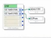
I tried to replicate the error message you are getting but didn't manage to, what I did find is that I don't need the E2Prom in the 'Hardware Configuration' tab in SigmaStudio, so I guess it is connecting directly to the DSP. Works on all three of my DSP boards.
I tried to replicate the error message you are getting but didn't manage to, what I did find is that I don't need the E2Prom in the 'Hardware Configuration' tab in SigmaStudio, so I guess it is connecting directly to the DSP. Works on all three of my DSP boards.
What addresses are displayed when you hook up the "ADAU1701" and "E2Prom" blocks? Do they match those shown in the video?
Exactly the same, I'm afraid!
Just rechecked my setup, switches in position 1, green lights fading on programmer. I have cut the 5V line between the programmer and DSP, allowed me to use a 5 pin din plug.
I tried to replicate the error message you are getting but didn't manage to, what I did find is that I don't need the E2Prom in the 'Hardware Configuration' tab in SigmaStudio, so I guess it is connecting directly to the DSP. Works on all three of my DSP boards.
Hmmm, thanks for checking! Is the 5v powerline cut essential?
I'm glad you clarified that the lights fade in and out andnot blink as many people say. That had me scratching my head for a while.
All very frustrating!
Not sure if cutting the line helps but is not needed when powering from the usb, it was over a year ago since I was trying to get them to talk reliably.
what I did find is that I don't need the E2Prom in the 'Hardware Configuration' tab in SigmaStudio, so I guess it is connecting directly to the DSP. Works on all three of my DSP boards.
Scrub that re E2Prom, would appear that it was still active even though showing as deleted.
Do you think my 1701 is blown and should be replaced as I misplaced some I2C wires and now the self boot is not working anymore? On SigmaStudio I can read and write the E2Prom and the DSP, so it seems to be problem with selfboot only. I have checked that WP/CLATCH pin is "1" (3v2) (also the SELFBOOT pin) so it should selfboot from eeprom which has correct data.
Haven't check with scope though, but it seems that DSP cannot pull either clock or data down when trying to work as master during the boot.
Guess I have to order a new one...
Haven't check with scope though, but it seems that DSP cannot pull either clock or data down when trying to work as master during the boot.
Guess I have to order a new one...

Well, in the end the board was replaced as faulty!
Anyway, I have a question regarding balanced outputs from this board.
Is it possible to use all 4 of the outputs for a stereo balanced pair? Logic suggests splitting the signal and then inverting one of them which would create a +&-. Is this idea too good to be true? It would be very handy going in to switching amps.
🙂
I'm using it all the time, simply invert one channel.
similarly you can use a stereo input as mono balanced in by subtracting the 2 inputs.
similarly you can use a stereo input as mono balanced in by subtracting the 2 inputs.
Hello all.
I wonder if someone can point me in the right direction, please?
I am trying to use a pot to control a peak filter for bass and I would like to add another for treble as well. Volume is being successfully controlled by a 10k pot as per the pdf which describes it.
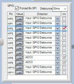
There is an example file that comes with SigmaStudio so I copied the group of components over and reassigned it for ADC0 which corresponds to MP9 (the first pot on the Sure board). However, when implemented the 2nd Order Filter immediately puts the curve the minimum and there is no control from Pot 1.
Can anyone see what I am missing?


(please ignore MP2, that was highlighted by mistake before I left this morning)
Absolutely brilliant, thanks! All working like a dream in that respect.
I wonder if someone can point me in the right direction, please?
I am trying to use a pot to control a peak filter for bass and I would like to add another for treble as well. Volume is being successfully controlled by a 10k pot as per the pdf which describes it.
There is an example file that comes with SigmaStudio so I copied the group of components over and reassigned it for ADC0 which corresponds to MP9 (the first pot on the Sure board). However, when implemented the 2nd Order Filter immediately puts the curve the minimum and there is no control from Pot 1.
Can anyone see what I am missing?
(please ignore MP2, that was highlighted by mistake before I left this morning)
I'm using it all the time, simply invert one channel.
similarly you can use a stereo input as mono balanced in by subtracting the 2 inputs.
Absolutely brilliant, thanks! All working like a dream in that respect.
Attachments

Hello all.
I wonder if someone can point me in the right direction, please?
I am trying to use a pot to control a peak filter for bass and I would like to add another for treble as well. Volume is being successfully controlled by a 10k pot as per the pdf which describes it.
There is an example file that comes with SigmaStudio so I copied the group of components over and reassigned it for ADC0 which corresponds to MP9 (the first pot on the Sure board). However, when implemented the 2nd Order Filter immediately puts the curve the minimum and there is no control from Pot 1.
Can anyone see what I am missing?
(please ignore MP2, that was highlighted by mistake before I left this morning)
Absolutely brilliant, thanks! All working like a dream in that respect.
I've not had a play, the zip file contains the original SureDSP firmware and the link is the TI hardware control application notes pdf:
https://www.analog.com/media/en/technical-documentation/application-notes/AN-951.pdf
Attachments
- Home
- Source & Line
- Digital Line Level
- New? Sure Electronics ADAU1701 Module