Funny how cables are still singled out when it comes to jitter.
Nevermind that usb "jitter" doesn't matter at all with async.
Nevermind that in the non-async modes, the timing of the host is probably worse by orders of magnitude that any deviation the cable could introduce.
Nevermind that the performance of the various USB receivers wrt audio clock generation are also all over the map.
Nevermind that the implementation of the receiver also affects its performance.
Nevermind that many DACs have asrc somewhere, making jitter in the interface a non-issue.
The poor cable still gets the heat.
I like analogies.
The USB link has to transport a number. It depends on the application what the receiver does with the number.
So. I am the transmitter and want the guy at the receiving end to chalk the number 7 on a blackboard.
I yell 'seven!' . But I can't yell very loud and the receiver guy has not so very good ears (the analogy for a bad cable) yet the guy hears '... even..' . Using some simple error detection and correction in his head he concludes I yelled 'seven' and chalks '7' on the blackboard.
100% correct data transmission through a not so good connection.
That helps you to get it Boky? 😉
The task of a USB link is to deliver the same numbers at the far end as were stuffed in at the near end. That's ALL. It doesn't matter what the numbers represent. A Mahler symphony, the recipe for lycee pizza, or last year's tax return forms. It's all just numbers. Once the number has been delivered correctly, the USB's task is over.
Jan
Have you ever tried two different USB cables in your audio system? If you have, were you able to tell the difference in sound?
OK, more stories, more handwaving, more dubious claims repeated, no data.
Figure 8 for you then, all the way....
From the fact that such a cable transports just a bunch of numbers, and that when the numbers come across correctly in any but a pathological cable, how can the same numbers lead to different sound?
OK, more stories, more handwaving, more dubious claims repeated, no data.
We live in an analogue world, “digital” signals are analogue signals that were labelled as “digital” with two logical voltage or current zones that represent “0” and “1”.
We can add ac interference signal of say 1Vpp to this “digital” signal and the data can still be recovered correctly. However, now we are not just receiving correct data but also ripple voltage.
The “digital” signal timing can also vary. If these timing fluctuations exceed predefined limits this will result in data corruption. Similar to the ripple on the “digital” signal we can also have certain amount of jitter in the “digital” signal while no data corruption occurs.
So we are NOT just receiving numbers, we receive numbers -and- ripple voltage -and- jitter.
USB also comes with a 5V bus voltage. It can also contain ripple voltage.
So things are not as black and white (digital) as it seems.
Starting at the USB audio source. In order to avoid comparing apple’s with oranges it helps to ensure playback is bit-perfect. In other words the -audio- data received by the DAC is the same as the -audio- data contained in the audio file. Some manufacturer’s include a bit-perfect test in their USB DACs to clear this issue.
USB bus power, some USB DACs are powered by the USB audio source -through- the USB interlink. Thicker or thinner power leads within the USB interlink can introduce a measurable difference in DC voltage (dynamic load dependent voltage drop) and or changing bus voltage interference spectrum on the DAC side.
USB audio sources produce interference (fundamentals plus harmonics) that end up on the USB bus power supply. This can be verified by a spectrum analyser. The interference spectrum of every computer - software - interlink combination is unique. One can even measure the influence of CPU load. Uncompressed WAV /AIFF require less processing power (and related interference) compared to compressed Apple Lossless / FLAC that require much more processing power (and related higher interference).
This USB bus power quality issue can be reduced by using a -self- powered DAC.
When connecting an USB audio device to an external DAC -without- suitable galvanical insulation, a ground loop is created. Ground loops couple interference into the DAC and connected audio components. The resulting interference on the audio signal can be verified by a spectrum analyser. In practice it causes audible hum or rattle in the speakers and it changes the DAC output spectrum. The ground loop spectrum can be changed by many factors, including USB interlink properties like reactance, capacitance dieelectric losses, shielding, the way the differential signal wires are twisted together (or not) and so on.
This USB ground loop issue can be fixed by using a battery powered laptop that is -not- electrically connected to anything else. We can also attempt to use (USB) isolators.
Isolators could be placed in the USB signal path (Analog devices Adum 4160). These will add significant jitter to the isolated USB signal and limit the sample rate to 96 KHz.
Isolators can also be placed in the I2S signal path. Some of the best chip isolators from NVE still add at least 100ps of jitter.
Finally we could use a 1:1 isolation transformer on the DAC output .
There are USB DACs based on isochronous or asynchronous USB audio transfer. Isochronous DACs recover the USB audio source clock using a PLL-based clock recovery system. This is -very- likely to cause USB audio source related jitter and interference issues as we don’t have access to a clean independent local clock signal. PLLs generate certain amount of jitter, the very best, used for this application produce approx. 50ps of intrinsic jitter. Jitter increases significantly during clock recovery. This isochronous setup will be highly sensitive to USB audio source and USB interlink properties.
Data corruption (there is no way of correcting data) seems to be a non issue. TI reported one error in an isochronous transmission every few weeks if I recall correctly.
Asynchronous USB DACs have a “clean” local masterclock that serves as DAC timing signal. The amount of data flowing from USB audio source to the asynchronous DAC is regulated in order to synchronize the USB audio source with the USB DAC. The advantage is that we now have some more control over clock signal quality.
So to sum things up we need following in order to improve USB audio performance:
1) Ensuring playback is bit-perfect.
2) Self powered DAC (USB audio source bus power is not used to power the DAC).
3) Suitable galvanical insulation between both, USB audio source and DAC.
4) Asynchronous USB audio DAC (local audio clock).
Ok all is fixed then, time for coffee,
Eh, no.
Let’s assume we did everything right (above list) and use an asynchronous XMOS USB audio receiver for example.
This is what is going to happen:
USB data plus interference on its amplitude plus timing fluctuations on its transients arrive at the DAC after struggling through a non-perfect USB interlink. The contained DATA is still clearly readable but the signal has become noisy.
This noisy serial signal enters a PHY de-serializer that feeds parallel DATA to the XMOS core’s. At this moment we polluted the receiver power supply and ground plane with USB audio source related interference.
Both, PHY and XMOS need clock signals to run, not just any clock signal, multiple of 13 MHz please. Let’s call this the -system clock-. The source interference crosstalks to this system clock and we have a modulated radio wave on our hands, it is modulated with source interference. Unless we use perfect screening, this interference is broadcasted and reaches each and every component in the DAC through EMI.
HF signals are not audible so why bother? The problem occurs when these modulated carrier waves get demodulated and then dump the contained audible interference right into the audio spectrum, like with a radio receiver. It only takes a single P-N junction to demodulate such amplitude modulated carrier.
Next we have some nice, low jitter masterclocks, the audio clocks. These are going to be used for our DAC timing signal …. somehow. But these will also receive EMI and the datasheet phase noise specs go down the drain.
This audio clock is either a multiple of 44.1 KHz or 48 KHz. So we basically require two audio clocks.
We could go for 22.5792 MHz and 24.576 MHz for example. The XMOS determines the incoming sample rate and selects the correct audio clock by means of a SEL signal. The XMOS produces interference too and the I/O pin enabling the masterclock output dumps this noise on the sensitive oscillator circuits through the clock buffer. The audio clock is not so clean annymore ….
The XMOS can only change the state of the I2S signals on it’s I/O pins when the -system- clock changes. The system clock frequency however is not an exact multiple of the -audio- clock. So things are not going to “fit” perfectly. After the audio clock changes state, there is a variable but specified guaranteed response time from the XMOS. This results in -very- high jitter on -all- I2S signals generated by the XMOS. This jitter is easy to measure with a spectrum analyser and even with an oscilloscope.
When we use these XMOS I2S output signals directly, we are rewarded by a truckload of jitter. Similar happens when using I2S outputs of a RaspBerrie pie for driving a DAC. If you want to have truckloads of jitter (timing) and interference (ripple) on the I2S signals, plus a nice ground loop, this is the way to do it.
This jitter is so severe that when generating a S/PDIF signal with the XMOS USB audio receiver, the connected S/PDIF receiver won’t even lock. So we are not talking about neglible jitter here as it causes data corruption with S/PDIF.
Because the variable response time is guaranteed (XMOS is a state machine processor), we can apply synchronous reclocking by using the -audio- clock once more. This comes with further increased phase noise levels through parastitics in the synchronous reclockers.
Jittery I2S signal -> D-flip-flop (clocked by the audio clock) -> “cleaned-up” I2S signal.
One -could- simply feed the jittery I2S signals into a DAC chip and pray that the DAC masterclock signal will cure all, somewhere deep inside that piece of silicon. In practice this is not going to work very well either.
One -could- add an extra FIFO buffer that collects I2S data from the XMOS and clocks it out with the audio clock. We basically applied synchronous reclocking while adding more unnecessary switching noise from the FIFO buffer components.
One -could divide-down the audio clock, generating BCK and or WS, but when the divider skips some pulses or starts at some random position we will end up with phase locking problems and related data corruption. On top of that we would also require a programmable divider for multiple sample rate support that in turn would have to be controlled by the XMOS.
So even a “simple” thing as “using the audio clock to clock the DAC” turns out to be rather problematic and there are different options that lead to different results.
In a perfect world with perfect parts we would have been able to block source jitter by synchronous reclocking and shield the circuits against EMI. We would have ground planes with zero impedance.
In the real world we have to accept degrading introduced by imperfect parts.
Here is a short list of frequencies (fundamentals / harmonics) produced by a single 24.576 MHz clock that would typically occur in a USB DAC, and related impedance of “only” 5pF stray capacitance:
24.576 Mhz, 5pF -> 1.29 K Ohms
49.152 Mhz, 5pF -> 647 Ohms
73.728 Mhz, 5pF -> 431 Ohms
98.304 Mhz, 5pF -> 323 Ohms.
122.88 Mhz, 5pF -> 259 Ohms.
147.456 Mhz, 5pF -> 215 Ohms
These “parasitics” are present between all pins of all chips used in a DAC. When added to the schematics we get a completely different picture of this truly -hopeless- situation. And these are only the parasitic capacitances, we also have parasitic inductance and coupling.
In our straight-forward XMOS USB receiver we already have 3 different oscillator frequencies plus harmonics, imagine what chaos this will produce in all parasitics present in a DAC.
-> The end result is a USB DAC that always sounds different, the sound changes with mains pollution, WIFI activity, CPU load (virus scanners, WAV/AIFF vs ALAC/FLAC, applicatios and so on), temperature (oscillator drift, parasitic capacitance change), humidity (high Ohmic bypass on the PCB), USB interlink properties and so on. All this despite bit-perfect playback.
This collection of “digital” crap in these bit togglers is so critical that the slightest microscopic change will already change its performance. Suitable measurements of all -relevant- parameters would back this up. In my humble opinion we haven’t even identified all major DAC parameters responsible for -perceived- sound quality yet.
Last edited:

Have you ever tried two different USB cables in your audio system? If you have, were you able to tell the difference in sound?
Sighted listening with expectation bias (you expect to hear a change) just proves how gullible your brain is.
Hi Jan,
There's no conventional error per se in asynch USB (as opposed to the CRC + re-send in sync).
However, at the USB receiver, there is additional processing called into action when signal integrity issues exist so as to recover the bits (or define the bits).
This extra processing affects the DAC chips. At least that's how John Swenson (who has also done in the past new linear power supplies for better SQ as I believe you have too) explains his findings.
So, you may get the bits exactly as they were sent after the USB interface has done its job, but the noise profile of one transmission with high signal integrity issues isn't the same where there is no or much lower signal integrity issues.
Now, one could opt for a Corning Optical USB cable, because then we do know that the SI is less of an issue theoretically and in practice.
On the other hand, one needs to hear or measure whether the inherent noise profile of the optical decoder/receptor makes a difference as well.
Others prefer regeneration, re-clocking, clean power at the reception.
Mileages may vary...
I have no idea what all this 'noise profile' stuff is all about. I just wish you or Boky would help me understand why the same numbers arriving at the DAC give rise to different sound (excluding jitter; I am assuming that the DAC takes care of that, unless this is what you mean?).
I agree that in the final analysis everything is analog, also the signal in the DAC cable. But it represents a number, the DAC want a number, and if the number comes over OK, who cares what the voltage and time parameters of the signal were?
It'really very simple: how can the same numbers going into the DAC lead to different sound coming out of it (except for jitter)? You must have thought about that?
Jan
Have you ever tried two different USB cables in your audio system? If you have, were you able to tell the difference in sound?
If you have no idea of the answer to my question, or if is to inconvenient to answer, just say so or don't reply. Don't dodge it with another question. It's called 'sensible discussion'.
Jan
We live in an analogue world, “digital” signals are analogue signals that were labelled as “digital” with two logical voltage or current zones that represent “0” and “1”.
We can add ac interference signal of say 1Vpp to this “digital” signal and the data can still be recovered correctly. However, now we are not just receiving correct data but also ripple voltage.
The “digital” signal timing can also vary. If these timing fluctuations exceed predefined limits this will result in data corruption. Similar to the ripple on the “digital” signal we can also have certain amount of jitter in the “digital” signal while no data corruption occurs.
So we are NOT just receiving numbers, we receive numbers -and- ripple voltage -and- jitter.
USB also comes with a 5V bus voltage. It can also contain ripple voltage.
So things are not as black and white (digital) as it seems.
[cut to save bandwidth]
If a cable is sooo bad that the numbers arriving at the end are really different that the numbers that went in, all hell will break loose and the sound will break up or gives ticks and crashes. Nothing subtle about it, and you do best to throw that cable away.
All you ripple and time skew and whatever can be what it is, if the numbers come over correctly, that's all that matters.
So far, I have asked a simple question that nobody had an answer for, and nobody had the guts to say, OK, maybe I was wrong.
All we get are 'possible this' and 'it's not b/w' etc.
Handwaving at it best.
Jan
Last edited:
Jan, just to clarify, the jitter in the delivered numbers is irrelevant unless it's so high that it causes packet loss. The only jitter that matters is at the DAC clock pin. I know you know this, I'm just removing the slight ambiguity in your phrasing.
And just to note (shock horror) that ODAC jitter spectrum was using a USB chip that does not support Async operation. It should be awful, unlistenable.
It's biggest flaw of course is that it's only $149 😛
It's biggest flaw of course is that it's only $149 😛
Jan, just to clarify, the jitter in the delivered numbers is irrelevant unless it's so high that it causes packet loss. The only jitter that matters is at the DAC clock pin. I know you know this, I'm just removing the slight ambiguity in your phrasing.
Yes of course, you are right.
Maybe react to the numerous posts 'I changed the cable and it clearly sounded different to me'.
Some of you may wonder why we give no significance to that. That's because we assume it is now general knowledge that perception is one of the worst ways you can 'prove' anything. Decades of perception and neuro-psychology research has made that abundantly clear.
This has been treated and explained and referred here also millions of times.
But maybe we forget too easy that new kids come on the block who are not aware of the implications, and if they are, are still in the phase to discover and/or accept how much your perception apparatus can and does trick you at almost any instant.
So, it's not because we don't read it. It's because we assume that this stuff is general knowledge. Apologies.
Jan
That is because it doesn't require much technical knowledge to buy and change a cable, so people change what they are capable of changing. All the other issues you mention are outside their control and, in some cases (demonstrated in this thread), outside their understanding.00940 said:The poor cable still gets the heat.
We live in an analogue world, “digital” signals are analogue signals that were labelled as “digital” with two logical voltage or current zones that represent “0” and “1”.
We can add ac interference signal of say 1Vpp to this “digital” signal and the data can still be recovered correctly. However, now we are not just receiving correct data but also ripple voltage.
The “digital” signal timing can also vary. If these timing fluctuations exceed predefined limits this will result in data corruption. Similar to the ripple on the “digital” signal we can also have certain amount of jitter in the “digital” signal while no data corruption occurs.
So we are NOT just receiving numbers, we receive numbers -and- ripple voltage -and- jitter.
USB also comes with a 5V bus voltage. It can also contain ripple voltage.
So things are not as black and white (digital) as it seems.
Starting at the USB audio source. In order to avoid comparing apple’s with oranges it helps to ensure playback is bit-perfect. In other words the -audio- data received by the DAC is the same as the -audio- data contained in the audio file. Some manufacturer’s include a bit-perfect test in their USB DACs to clear this issue.
USB bus power, some USB DACs are powered by the USB audio source -through- the USB interlink. Thicker or thinner power leads within the USB interlink can introduce a measurable difference in DC voltage (dynamic load dependent voltage drop) and or changing bus voltage interference spectrum on the DAC side.
USB audio sources produce interference (fundamentals plus harmonics) that end up on the USB bus power supply. This can be verified by a spectrum analyser. The interference spectrum of every computer - software - interlink combination is unique. One can even measure the influence of CPU load. Uncompressed WAV /AIFF require less processing power (and related interference) compared to compressed Apple Lossless / FLAC that require much more processing power (and related higher interference).
This USB bus power quality issue can be reduced by using a -self- powered DAC.
When connecting an USB audio device to an external DAC -without- suitable galvanical insulation, a ground loop is created. Ground loops couple interference into the DAC and connected audio components. The resulting interference on the audio signal can be verified by a spectrum analyser. In practice it causes audible hum or rattle in the speakers and it changes the DAC output spectrum. The ground loop spectrum can be changed by many factors, including USB interlink properties like reactance, capacitance dieelectric losses, shielding, the way the differential signal wires are twisted together (or not) and so on.
This USB ground loop issue can be fixed by using a battery powered laptop that is -not- electrically connected to anything else. We can also attempt to use (USB) isolators.
Isolators could be placed in the USB signal path (Analog devices Adum 4160). These will add significant jitter to the isolated USB signal and limit the sample rate to 96 KHz.
Isolators can also be placed in the I2S signal path. Some of the best chip isolators from NVE still add at least 100ps of jitter.
Finally we could use a 1:1 isolation transformer on the DAC output .
There are USB DACs based on isochronous or asynchronous USB audio transfer. Isochronous DACs recover the USB audio source clock using a PLL-based clock recovery system. This is -very- likely to cause USB audio source related jitter and interference issues as we don’t have access to a clean independent local clock signal. PLLs generate certain amount of jitter, the very best, used for this application produce approx. 50ps of intrinsic jitter. Jitter increases significantly during clock recovery. This isochronous setup will be highly sensitive to USB audio source and USB interlink properties.
Data corruption (there is no way of correcting data) seems to be a non issue. TI reported one error in an isochronous transmission every few weeks if I recall correctly.
Asynchronous USB DACs have a “clean” local masterclock that serves as DAC timing signal. The amount of data flowing from USB audio source to the asynchronous DAC is regulated in order to synchronize the USB audio source with the USB DAC. The advantage is that we now have some more control over clock signal quality.
So to sum things up we need following in order to improve USB audio performance:
1) Ensuring playback is bit-perfect.
2) Self powered DAC (USB audio source bus power is not used to power the DAC).
3) Suitable galvanical insulation between both, USB audio source and DAC.
4) Asynchronous USB audio DAC (local audio clock).
Ok all is fixed then, time for coffee,
Eh, no.
Let’s assume we did everything right (above list) and use an asynchronous XMOS USB audio receiver for example.
This is what is going to happen:
USB data plus interference on its amplitude plus timing fluctuations on its transients arrive at the DAC after struggling through a non-perfect USB interlink. The contained DATA is still clearly readable but the signal has become noisy.
This noisy serial signal enters a PHY de-serializer that feeds parallel DATA to the XMOS core’s. At this moment we polluted the receiver power supply and ground plane with USB audio source related interference.
Both, PHY and XMOS need clock signals to run, not just any clock signal, multiple of 13 MHz please. Let’s call this the -system clock-. The source interference crosstalks to this system clock and we have a modulated radio wave on our hands, it is modulated with source interference. Unless we use perfect screening, this interference is broadcasted and reaches each and every component in the DAC through EMI.
HF signals are not audible so why bother? The problem occurs when these modulated carrier waves get demodulated and then dump the contained audible interference right into the audio spectrum, like with a radio receiver. It only takes a single P-N junction to demodulate such amplitude modulated carrier.
Next we have some nice, low jitter masterclocks, the audio clocks. These are going to be used for our DAC timing signal …. somehow. But these will also receive EMI and the datasheet phase noise specs go down the drain.
This audio clock is either a multiple of 44.1 KHz or 48 KHz. So we basically require two audio clocks.
We could go for 22.5792 MHz and 24.576 MHz for example. The XMOS determines the incoming sample rate and selects the correct audio clock by means of a SEL signal. The XMOS produces interference too and the I/O pin enabling the masterclock output dumps this noise on the sensitive oscillator circuits through the clock buffer. The audio clock is not so clean annymore ….
The XMOS can only change the state of the I2S signals on it’s I/O pins when the -system- clock changes. The system clock frequency however is not an exact multiple of the -audio- clock. So things are not going to “fit” perfectly. After the audio clock changes state, there is a variable but specified guaranteed response time from the XMOS. This results in -very- high jitter on -all- I2S signals generated by the XMOS. This jitter is easy to measure with a spectrum analyser and even with an oscilloscope.
When we use these XMOS I2S output signals directly, we are rewarded by a truckload of jitter. Similar happens when using I2S outputs of a RaspBerrie pie for driving a DAC. If you want to have truckloads of jitter (timing) and interference (ripple) on the I2S signals, plus a nice ground loop, this is the way to do it.
This jitter is so severe that when generating a S/PDIF signal with the XMOS USB audio receiver, the connected S/PDIF receiver won’t even lock. So we are not talking about neglible jitter here as it causes data corruption with S/PDIF.
Because the variable response time is guaranteed (XMOS is a state machine processor), we can apply synchronous reclocking by using the -audio- clock once more. This comes with further increased phase noise levels through parastitics in the synchronous reclockers.
Jittery I2S signal -> D-flip-flop (clocked by the audio clock) -> “cleaned-up” I2S signal.
One -could- simply feed the jittery I2S signals into a DAC chip and pray that the DAC masterclock signal will cure all, somewhere deep inside that piece of silicon. In practice this is not going to work very well either.
One -could- add an extra FIFO buffer that collects I2S data from the XMOS and clocks it out with the audio clock. We basically applied synchronous reclocking while adding more unnecessary switching noise from the FIFO buffer components.
One -could divide-down the audio clock, generating BCK and or WS, but when the divider skips some pulses or starts at some random position we will end up with phase locking problems and related data corruption. On top of that we would also require a programmable divider for multiple sample rate support that in turn would have to be controlled by the XMOS.
So even a “simple” thing as “using the audio clock to clock the DAC” turns out to be rather problematic and there are different options that lead to different results.
In a perfect world with perfect parts we would have been able to block source jitter by synchronous reclocking and shield the circuits against EMI. We would have ground planes with zero impedance.
In the real world we have to accept degrading introduced by imperfect parts.
Here is a short list of frequencies (fundamentals / harmonics) produced by a single 24.576 MHz clock that would typically occur in a USB DAC, and related impedance of “only” 5pF stray capacitance:
24.576 Mhz, 5pF -> 1.29 K Ohms
49.152 Mhz, 5pF -> 647 Ohms
73.728 Mhz, 5pF -> 431 Ohms
98.304 Mhz, 5pF -> 323 Ohms.
122.88 Mhz, 5pF -> 259 Ohms.
147.456 Mhz, 5pF -> 215 Ohms
These “parasitics” are present between all pins of all chips used in a DAC. When added to the schematics we get a completely different picture of this truly -hopeless- situation. And these are only the parasitic capacitances, we also have parasitic inductance and coupling.
In our straight-forward XMOS USB receiver we already have 3 different oscillator frequencies plus harmonics, imagine what chaos this will produce in all parasitics present in a DAC.
-> The end result is a USB DAC that always sounds different, the sound changes with mains pollution, WIFI activity, CPU load (virus scanners, WAV/AIFF vs ALAC/FLAC, applicatios and so on), temperature (oscillator drift, parasitic capacitance change), humidity (high Ohmic bypass on the PCB), USB interlink properties and so on. All this despite bit-perfect playback.
This collection of “digital” crap in these bit togglers is so critical that the slightest microscopic change will already change its performance. Suitable measurements of all -relevant- parameters would back this up. In my humble opinion we haven’t even identified all major DAC parameters responsible for -perceived- sound quality yet.
Funnily enough it has been possible to engineer USB interfaces were these issues are all addressed, its called signal integrity engineering, and EMC engineering and power delivery system integrity engineering...
Wot you describe in your last two paragraphs is not something that has been engineered, but hell this is the silly world of audio, were engineering is a bad word.
Lots of words and no data. Care to back up all that conjecture with a graph or two?
First I pointed out that there are USB audio sources that may or may not offer bit-perfect playback. I can proove that by means of a bit-perfect test:
Audio test file (WAV / FLAC) that contains a sawtooth shape test signal that sequentially scans through all 65,536 (16 bits) or 16,777,216 (24 bits) values. XMOS checks if all correct values are received. If not the signal has been tampered with and playback is not bit-perfect. This is a go - no go test that offers hard evidence at any given time, if playback is still bit-perfect.
Since the majority of USB DACs is driven by Windows there is a very good reason to verify if playback is bit-perfect before starting to compare USB DACs and drawing conclusions.
I also pointed out that there are different types of USB DACs:
- Self powered USB DACs, Metrum pavane for example.
- USB bus powered USB DACs, Audio quest dragonfly & beetle for example.
- Isochronous USB DACs based on the PCM2707 for example. These are sensitive to USB audio source jitter because the USB audio source clock is recovered by a PLL
- Asynchronous USB DACs based on TAS1020 or XMOS for example, these are less sensitive to USB audio source jitter because these use a local masterclock.
- Non-isolated USB DACs that create ground loops and are sensitive to USB audio source interference.
- Isolated USB DACs that are less sensitive to USB audio source interference because the ground loop is prevented by isolators.
Finally I attempted to show that parts are imperfect and that it is impossible to obtain perfect performance (zero jitter sensitivity) using such parts. USB DAC circuits already pick up interference as soon as the differential USB signal enters the first chip, the PHY in the example I gave you. Then interference gradually rises and degrade the masterclock. Once the masterclock is degraded, it’s a lost case.
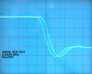
I attached an oscillogram. It shows the BCK signal at the XMOS asynchronous USB receiver I2S output pin. Time division setting 5ns/div. Everyone who has an XMOS USB receiver can verify this, measure directly on the XMOS output pin.
Like I said the difference between multiples of the 13 MHz system clock and the 22.5792 MHz audio clock results in heavy jitter. Here it is approx. 2 sub divisions or 2ns or 2000ps peak to peak. I would call this very high jitter as I stated in my post and here is an oscillogram to back this up.
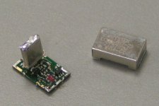
I recently bought these CCHD-597 ultra low phase noise masterclocks based on datasheet specs.
http://www.crystek.com/crystal/spec-sheets/clock/cchd-957.pdf
After several failed attempts with two of these clocks to achieve low jitter and related high sound quality with it, I decided to find out why this clock performed so badly and opened it.
Inside is a plain crystal oscillator based on this NAND gate:
https://www.fairchildsemi.com/datasheets/NC/NC7S00.pdf
With this output buffer:
https://www.fairchildsemi.com/datasheets/NC/NC7SP126.pdf
There isn’t even a ferrite bead or some kind of power supply filter inside, just a dirt cheap oscillator that probably doesn’t cost more than a dollar on parts.
So much for graphs.
Graphs won’t tell you what audible advantages or disadvantages to expect, because these jitter graphs are based on single or dual test tones (fundamentals). Music is infinitely more complex, it has a fast changing dynamic spectrum that creates the biggest problems in any DAC. The jitter graph won’t cover this because it only shows the DAC jitter response with these test signals only, it doesn’t show what happens when the data content and spectrum are infinitely more complex.
An example, power amplifier of an established brand plays without problems (it has excellent specs). But when that specific track is played the protection kicks in, shutting down the amplifier and you no longer have sound. This issue didn’t show up in the measurements or the manufacturer would have fixed it. This shows that there still can be significant problems despite excellent specs. This s why I mentioned that there are more relevant measurements necessary in order to reveal DAC issues that do not show with standard measurements.
I now use a jitter to audio converter. It basically consists of a tunable narrow bandwidth crystal filter and a demodulator. Now one can actually -hear- the jitter spectrum ,at least the part that is of interest for audio playback. PLLs generate static noise as if standing near the Niagara falls. Crystal masterclocks are much more quiet and more amplification is required to get down to the noise floor. There is a clearly audible difference in phase noise spectrum when audio streaming is started. One can hear heavily distorted -fragments- of music within the noise. This is a sign of deterministic (data related) jitter that causes most degrading.
Then there is A/D conversion jitter caused by the master clock that's used for conversion. This A/D conversion clock jitter is fused to the sample numbers as the signal is sampled slightly too soon or slightly too late resulting in the wrong sample value.
When it would be possible to construct a zero jitter USB DAC, you would have the full impact of A/D conversion jitter and still have degraded sound, especially with recordings made with sub optimal master clocks.
So aiming for lowest jitter might not lead to desired results either.
When a USB DAC really performs as it should, you would have highly involving music with emotional impact that's recognised within seconds, instead of just sound where you would have to concentrate heavily in order to detect some traces of real music in it.
Attachments
First I pointed out that there are USB audio sources that may or may not offer bit-perfect playback. I can proove that by means of a bit-perfect test:
Good. Please prove it. We await with interest. I posted the jitter spectrum of the non async, USB powered ODAC for your comments as well.
Thinking more and writing less may just help you get your point across clearly as at the moment I am not sure, especially when you start talking about ADC jitter.
Of course as you sell audiophile products your information is not (like many others who sell to an audiophile market) is not biased towards promoting the myths and keeping the true believers believing....
EC designs - XTOS Info
Oddly the in depth technical information is missing. Still €300 for a USB to toslink converter. Nice work if you can get it.
Oddly the in depth technical information is missing. Still €300 for a USB to toslink converter. Nice work if you can get it.
Just a reminder on terminology: all USB audio data transfers are isochronous (as opposed to bulk, interrupt and control modes).
They are then divided in three synchronization types : synchronous (almost never used except in very cheap receivers), adaptive and asynchronous.
For more details, section 5.12.4 of this document explains how those three synchronization types deal with clocking: http://www.pjrc.com/teensy/beta/usb20.pdf
- Status
- Not open for further replies.
- Home
- Source & Line
- Digital Line Level
- Is jitter an issue with usb signals ?