a quickie project that can be integrated into your own DIY dac or even a commercial one. you need 5v, wordclock (from an spdif rx chip's output, for example; can be 3.3v or 5v based) and optionally a lock-on led wire.
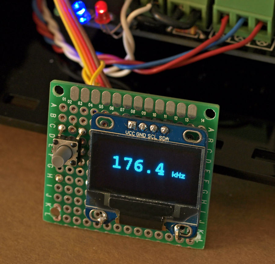
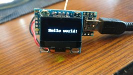
the oled display is a $10 part and is pretty common on ebay and other places. controller is the arduino nano, for simplicity (cost of that is $5 or less, including usb interface). the button is to turn the display on/off and is optional.
if there is interest, I can post the arduino source code. maybe even get small boards made (group buy).
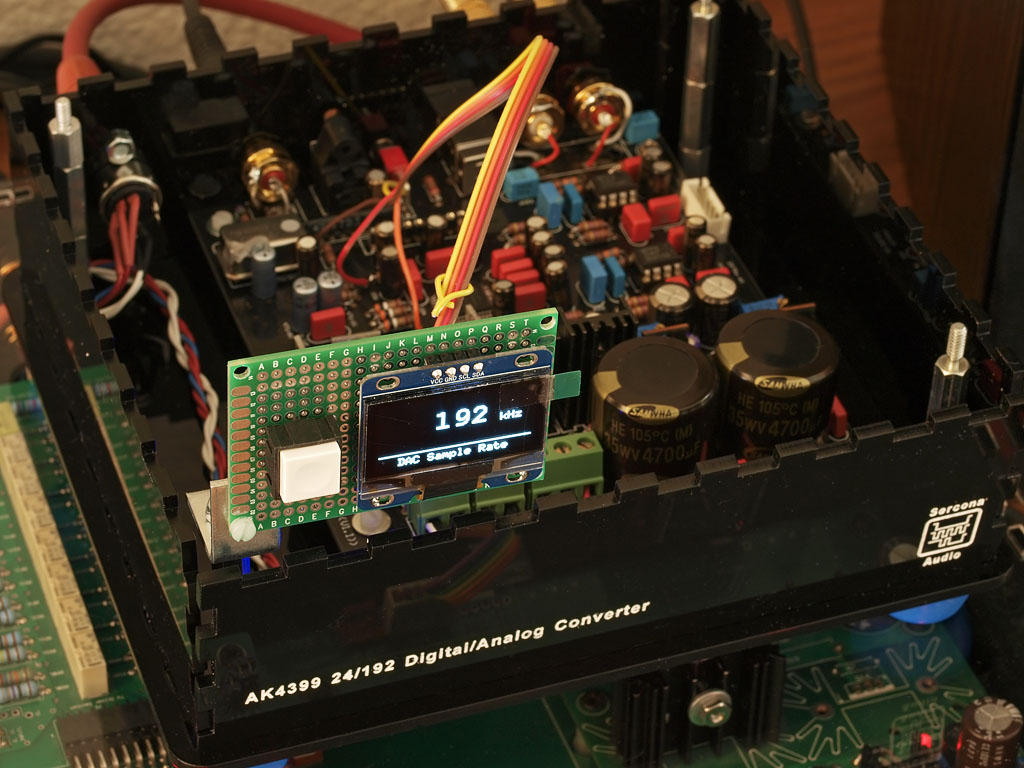
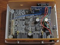
here, I have an ebay ak4399 dac with this board added on (clearly its not permanently mounted, lol; but just put there for debug and development). you can pick a .96" or 1.3" oled display, and they come in white or blue. white works well when you put it behind a color plastic filter.
its also not hard to convert that button into an input selector button.
the oled display is a $10 part and is pretty common on ebay and other places. controller is the arduino nano, for simplicity (cost of that is $5 or less, including usb interface). the button is to turn the display on/off and is optional.
if there is interest, I can post the arduino source code. maybe even get small boards made (group buy).
here, I have an ebay ak4399 dac with this board added on (clearly its not permanently mounted, lol; but just put there for debug and development). you can pick a .96" or 1.3" oled display, and they come in white or blue. white works well when you put it behind a color plastic filter.
its also not hard to convert that button into an input selector button.

schematic is simple. I'll describe it since its too simple to even draw 😉
pin5 is the wordclock input; has to be pin5 for the freq counter software lib.
i2c pins go to the clock/data on the oled. on the 328 arduino chip, its the top 2 pins on the dip pkg (28 and 27). match those up with clock and data on oled. add 5v and gnd to oled. on arduino chip, add resonator or xtal as usual. jumper the ground on one side of the chip to gnd on the other (I think the 2nd ground on the 328 chip is the digital vs analog gnd; but I always connect them). I don't connect aref or avcc since I don't need them.
button goes from pin11 (arduino D11, that is) to gnd. there is a pullup in software for that button.
I think that's it. wordclock goes on D5 of the arduino and you may or may not need a 74hc14 or similar chip but I didn't. a 3.3v or 5v wordclock should be enough for the 5v arduino.
be sure your oled is 5v. mine are but some are 3.3v. similarly, be sure the i2c lines on the oled are 5v tolerant.
I just built a 2nd one. I programmed a blank 328 atmega chip on my programmer, moved it to a perf board and wired things up as I described. an hour later, it powers on and says hello. just the resonator, a .1 bypass on 5v/gnd, the button and oled and that's enough to verify the circuit comes on. take a freq generator and make sure its output is NOT over 5v (!) and give it spdif freqs like 32, 44.1, 48khz and so on, and the display should show the nearest standard value.
I'll post a url to the source once I upload it. should be ready to post in a day or two, once I test this out a bit more and make sure I didn't forget anything.
eventually I hope to get this running on a small attiny chip, but the freq counter code I have is meant for the actual 328 atmega and so I continue to 'waste' those, for the time being.
just built a 2nd one 😉
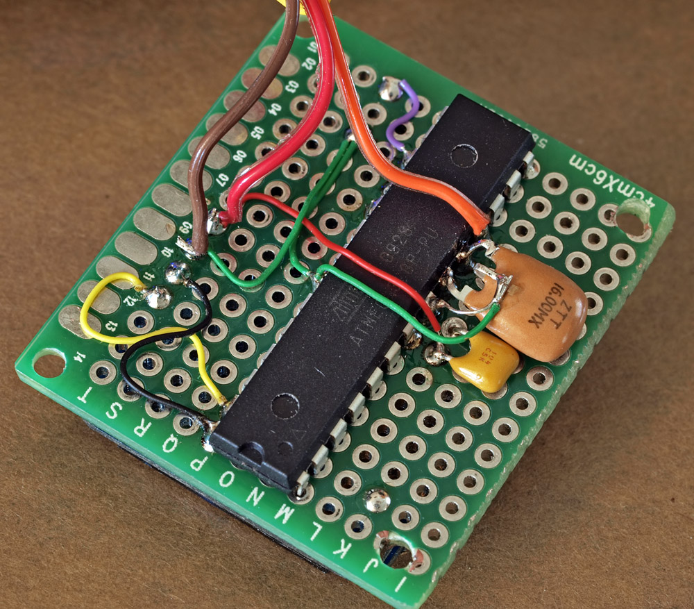
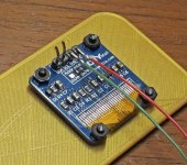
this uses discrete atmega 328 chip, 28pin skinny dip with cheap 16mhz resonator. ie, I did not use the convenient nano modules, I used the regular old blank 328 chip. there is really not much to this!
the 3 wires leaving it: red is 5v, brown is gnd and orange is wordclock in.
I bet a custom smd board could be made that would be the same size as the smallest oled display. then, it would fit into even more dac and switch (and maybe avr) panels.
I don't have a coin in there to show scale, but the board is standard .1" holes, so you can figure out how big that board is and how big an opening you'd need for the oled display (the visible part is much less than the whole glass, so your front panel should have a smaller opening than this display would have you think.)
Last edited:
Hi @linuxworks - could you post/send me the source code to this project? Would love to recreate it!
Thanks!
Thanks!
I would be interested in a PCB/finished product.
I am not up to speed with Arduino programming so a finished product would be great.
P.
I am not up to speed with Arduino programming so a finished product would be great.
P.
let me dig up the code, clean it up a bit and I'll post it.
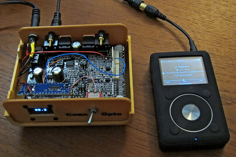
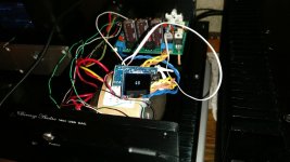
I recently made a 3d printed box to house an existing spdif transceiver demo board, so you don't have to 'build' a lot to get the sampelrate display:
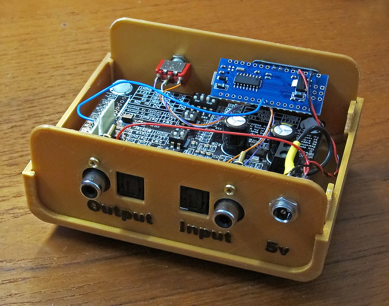
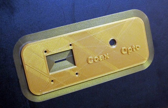
the case is regular PLA from my 3d printer and its an open source design, too.
on the middle photo, the blue pcb hanging in the air (air wired) is the arduino nano and it is supported by 2 pins (i2c) on the oled display. its a mounting hack to be sure, but it works and it fits inside this small box without taking up any more room. it taps into wordclock on the i2s line on that wolfson repeater board.
the 'circuit' is really simple and I'm thinking of making a very small backpack for the oled display that would hold the arduino (not a nano, but an arduino chip, its xtal and some small parts for support). may not even have to be 2layers, it would be so simple.
the demo board can be found on ebay from 'sure electronics' and if you search on wm8804 (or 8805) it should come up. its around $20 for the board and while its a large board for what it does, it sure does give a fast and easy way to prototype this.
if there is interest, a follow-on board could be made that would have both the arduino and some kind of spdif receiver chip. that would save having to get hold of the Sure brand board and the size of the chassis could be even smaller.
I still like the backpack idea for the samplerate display; so that just the display part could be diy integrated into existing dacs; rather than putting this in its own box.
and the Sure board also is a true pass-thru, so it will show the spdif rate and also reclock the audio from input selected port to BOTH output ports.
I recently made a 3d printed box to house an existing spdif transceiver demo board, so you don't have to 'build' a lot to get the sampelrate display:
the case is regular PLA from my 3d printer and its an open source design, too.
on the middle photo, the blue pcb hanging in the air (air wired) is the arduino nano and it is supported by 2 pins (i2c) on the oled display. its a mounting hack to be sure, but it works and it fits inside this small box without taking up any more room. it taps into wordclock on the i2s line on that wolfson repeater board.
the 'circuit' is really simple and I'm thinking of making a very small backpack for the oled display that would hold the arduino (not a nano, but an arduino chip, its xtal and some small parts for support). may not even have to be 2layers, it would be so simple.
the demo board can be found on ebay from 'sure electronics' and if you search on wm8804 (or 8805) it should come up. its around $20 for the board and while its a large board for what it does, it sure does give a fast and easy way to prototype this.
if there is interest, a follow-on board could be made that would have both the arduino and some kind of spdif receiver chip. that would save having to get hold of the Sure brand board and the size of the chassis could be even smaller.
I still like the backpack idea for the samplerate display; so that just the display part could be diy integrated into existing dacs; rather than putting this in its own box.
and the Sure board also is a true pass-thru, so it will show the spdif rate and also reclock the audio from input selected port to BOTH output ports.
Ah, amazing! That looks fantastic. I'm also planning on using one of those standard 128x64 OLED displays, so looking forward to the Arduino code. Fantastic - thanks so much!
Cool project, just ordered a few displays and arduino nanos. Can you please send me the code?
Best rgds
Yngve
Best rgds
Yngve
schematic is simple. I'll describe it since its too simple to even draw 😉
pin5 is the wordclock input; has to be pin5 for the freq counter software lib.
i2c pins go to the clock/data on the oled. on the 328 arduino chip, its the top 2 pins on the dip pkg (28 and 27). match those up with clock and data on oled. add 5v and gnd to oled. on arduino chip, add resonator or xtal as usual. jumper the ground on one side of the chip to gnd on the other (I think the 2nd ground on the 328 chip is the digital vs analog gnd; but I always connect them). I don't connect aref or avcc since I don't need them.
button goes from pin11 (arduino D11, that is) to gnd. there is a pullup in software for that button.
I think that's it. wordclock goes on D5 of the arduino and you may or may not need a 74hc14 or similar chip but I didn't. a 3.3v or 5v wordclock should be enough for the 5v arduino.
be sure your oled is 5v. mine are but some are 3.3v. similarly, be sure the i2c lines on the oled are 5v tolerant.
I just built a 2nd one. I programmed a blank 328 atmega chip on my programmer, moved it to a perf board and wired things up as I described. an hour later, it powers on and says hello. just the resonator, a .1 bypass on 5v/gnd, the button and oled and that's enough to verify the circuit comes on. take a freq generator and make sure its output is NOT over 5v (!) and give it spdif freqs like 32, 44.1, 48khz and so on, and the display should show the nearest standard value.
I'll post a url to the source once I upload it. should be ready to post in a day or two, once I test this out a bit more and make sure I didn't forget anything.
eventually I hope to get this running on a small attiny chip, but the freq counter code I have is meant for the actual 328 atmega and so I continue to 'waste' those, for the time being.
Hi Bryan - nice job on this. I was interested in this kind of thing a year or two ago (did we talk about it offline???) when I was still thinking about mucking around with hardware. Needless to say, I am interested in your implementation. Are you counting the wordclock frequency directly using the 328? I had envisioned using a decade counter or the like to slow down the clock rate and make it more easily countable, and wonder if direct counting would still work at the highest samples rates. Have you tested it at 192k?
hi charlie, yes, counting wordclock on the 328 atmega chip. works fine up to 192k, maybe beyhond but I don't have files higher than that 😉
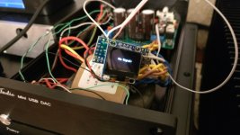
some photos of my 2nd build with more detailed close-ups.
some notes:
1) this is a hack, but it works and its simple to build
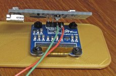
2) bend (carefully) the 2 i2c (clock/data) pins on the oled display. I used the smaller oled at .96" since its more common than the 1.3" one and it fits easier in smaller places. my 3d print file is designed for this size, also.
3) run power/gnd to the oled display as shown. those tie directly to the +5v/gnd on the arduino nano board
4) the oled display holds the nano up by those 2 metal pins on the 4 pin connector. make sure the bend is at the right angle so the nano does not touch the spdif switch module or the chassis
5) on the arduino, pin5 is the 'freq counter' pin input. only pin 5. you'll see a wire from the wordclock on one end of the switch board to the arduino; that's the only wire that is needed to count samplerate. (better design is to buffer the wordclock with a gate but this direct connection does seem to work ok)
6) I hacked the input select by moving both dip switches to 'off' on the selector block and running 3 wires to a spdt switch. better design is to logic switch this or something else, but again, this seems to work ok.
I will upload the code and 3d .stl file in another post.
some photos of my 2nd build with more detailed close-ups.
some notes:
1) this is a hack, but it works and its simple to build
2) bend (carefully) the 2 i2c (clock/data) pins on the oled display. I used the smaller oled at .96" since its more common than the 1.3" one and it fits easier in smaller places. my 3d print file is designed for this size, also.
3) run power/gnd to the oled display as shown. those tie directly to the +5v/gnd on the arduino nano board
4) the oled display holds the nano up by those 2 metal pins on the 4 pin connector. make sure the bend is at the right angle so the nano does not touch the spdif switch module or the chassis
5) on the arduino, pin5 is the 'freq counter' pin input. only pin 5. you'll see a wire from the wordclock on one end of the switch board to the arduino; that's the only wire that is needed to count samplerate. (better design is to buffer the wordclock with a gate but this direct connection does seem to work ok)
6) I hacked the input select by moving both dip switches to 'off' on the selector block and running 3 wires to a spdt switch. better design is to logic switch this or something else, but again, this seems to work ok.
I will upload the code and 3d .stl file in another post.
Attachments

code submitted to github:
GitHub - sercona/arduino-spdif-samplerate-display: Arduino (atmega 'nano' specific) based digital audio (spdif) sample rate display from i2s word-clock input
initial version; should build ok on current arduino IDE. download and install (via library manager inside arduino IDE) the u8glib library.
let me know if you have problems or questions.
enjoy 😉
I'm having a little trouble here.
It seem to be working, but the display show 48 all the time. I tried connecting my computer to the DAC and select different sample rates, but it only say 48.
This is the DAC I'm using.
DAC: CS4398 with CS8416+CM102s
I connected the frequency counter to Pin 28 "OLRCK" on the CS8416. Is that the correct pin?
Datasheet below.
http://www.mouser.com/ds/2/76/CS8416_F3-1132340.pdf
Best rgds
Yngve
Attachments
Last edited:
You sir, are a scholar and a gentleman.
 Thank you! Testing it out this weekend.
are you able to get hold of a freq counter or scope?
remember that many dacs or spdif receivers are 3.3v based. I've been able to directly couple the wordclock from a 3.3v source to my 5v based arduino and its always worked, but its not the right way to do it. a 74hc14 (or similar) is a good way to do it. somewhat high input Z, the cmos chip can run at 5v for output and it can sense a 3.3v signal just fine.
check to make sure your dac's ground is tied to the arduino ground, too.
and don't run the i2s wordclock on a long dangly wire. or, again, buffer with a chip close to the wordclock line and run the long dangly wire from the OUTPUT of the buffer, so that it won't mess with the edges of the actual wordclock.
if you have a function generator that you can dial in 44.1k and 48k (etc) you can test the arduino side without the dac.
and remember, ONLY pin5 on the arduino (D5, not literally pin5 on the DIP chip) is what you connect to. its the only pin I know of that can work with the freq counter library that I use.
I'm having a little trouble here.
It seem to be working, but the display show 48 all the time. I tried connecting my computer to the DAC and select different sample rates, but it only say 48.
This is the DAC I'm using.
DAC: CS4398 with CS8416+CM102s
I connected the frequency counter to Pin 28 "OLRCK" on the CS8416. Is that the correct pin?
Datasheet below.
http://www.mouser.com/ds/2/76/CS8416_F3-1132340.pdf
Best rgds
Yngve
have to ask this: are you SURE your computer is not forcing a resample of 48k?
I've been there, myself. this is why I created this display! some sound cards are sneaky ;(
I was listening to music and it should have been 44.1 but it showed 48. turns out my sound card was set to force it. an easy option to change but it wasn't set that way by default. maybe it had the last thing I was listening to (movies are usually 48k) and it was a 'sticky' setting, somehow.
so, be sure your source really is at the rate you think it is. a real freq counter on LR clock will show the truth.
I'm having a little trouble here.
It seem to be working, but the display show 48 all the time. I tried connecting my computer to the DAC and select different sample rates, but it only say 48.
This is the DAC I'm using.
DAC: CS4398 with CS8416+CM102s
I connected the frequency counter to Pin 28 "OLRCK" on the CS8416. Is that the correct pin?
Datasheet below.
http://www.mouser.com/ds/2/76/CS8416_F3-1132340.pdf
Best rgds
Yngve
The computer was connected with USB and it seems like the CM102 is forcing 48kHz.
The other source I use is a cheap streamer connected on toslink. I expected varying sample rate from this one, however I was wrong.
I just connected a cd-player to the DAC and the counter instantly switched to 44.1kHz. 🙂
The other source I use is a cheap streamer connected on toslink. I expected varying sample rate from this one, however I was wrong.
I just connected a cd-player to the DAC and the counter instantly switched to 44.1kHz. 🙂
- Home
- Source & Line
- Digital Line Level
- spdif sample rate display, OLED style