Hey Spzzzzkt, not sure if this is useful or interesting to you but just in case...
Attached is an initial Matlab script that performs and compares (in the time-domain) upsampling of an "Audio.wav" file via FFT zero insertion and FIR interpolation. Presently only channel 1 is calculated.
At the moment, the comparison is only a presentation of waveforms of 'n' samples at the start, end, and middle. Could modify it to calculate a difference between samples to determine 'error' value or %... Presuming 14 bit ENOB, you'd expect any PCM value difference of >= 0.000122 to be audible right?
Presuming comparison may be useful to assess FIR filter performance since FFT zero insertion upsampling is meant to be an 'exact' method (in the middle anyways, not at the start or end of vectors).
Attachments
thanks aive... I'll have a look at them.
I still think the zero insertion is more to do with the way the incoming data passes between clock domains, than specific processing. I'll try to do a diagram of what I mean...
Just been having a listen to a few filters, the TrueNOS, NewNOS, EQHQv2r1 and a few other things I've been messing around with like Nyquist filters done with an Ultra-spherical window.
I don't usually bother with the NOS filters, beyond a quick half a track listen every now and then. Anyway I think there is very little to pick between the "True"NOS and NewNOS in sound quality - they sound pretty well identical to my ears.
What I did notice that I hadn't really picked up on previously - possibly due the test tracks I had on when I was comparing - was that the NOS frequency roll-off manifests as a artifical sense of added depth to the soundstage. Female vocals very obviously move back in the sound stage relative to bass and drums which I guess is to be expected. I'd bet that if you built a brick wall filter that incorporated a sinc roll-off through the audio band you'd get the same kind of "improved" depth of sound stage. But ultimately it's faux-depth.
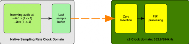
I hope this will illustrate what I think is happening with the TrueNOS (and upsampling in general) a bit more clearly...
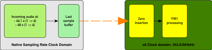
You have incoming data received by the DAM, and processed at the native sampling rate. 44.1, 88.2, 176.4, 352.8 and so on. The last received piece of data will sit in a buffer until the buffer has new data loaded at the next clock cycle at the incoming clock rate.
The next stage of processing is always running at the x8 rates - 352.8 or 384kHz. Based on what's happening with the TrueNOS filter, I'm fairly certain that the buffer from the input stage is read on every clock cycle which means with a 44.1kHz input data rate the buffered data will be read 8 times before it is updated.
The zero insert coefficient is basically setting how many zeros are inserted after the initial sample is read. If it's set for "1" there is no replacement/insertion done, so the second stage will end up with 8 copies of the original sample, assuming a 44.1/48 clock rate.
So for 44.1/48 you end up with:
x1 - 1 1 1 1 1 1 1 1
x2 - 1 0 1 0 1 0 1 0
x4 - 1 0 0 0 1 0 0 0
x8 - 1 0 0 0 0 0 0 0
So by setting zero insert coefficient to 1 the second stage of the DAC reads the input buffer every clock cycle, and there is no need to convolve with an 8 x 1.000 value "filter" to reconstruct the original samples because the samples data is already there...
Attachments
Last edited:
...was that the NOS frequency roll-off manifests as a artifical sense of added depth to the soundstage. Female vocals very obviously move back in the sound stage relative to bass and drums which I guess is to be expected. I'd bet that if you built a brick wall filter that incorporated a sinc roll-off through the audio band you'd get the same kind of "improved" depth of sound stage. But ultimately it's faux-depth.
IMO you loose yourself into wild speculations and guesses. Finally you "ultimately" set this questionable stuff into stone. Scientific?? No. That's audiophile hocus pocus.
Pretty much everything on a mix/recording is artificially made up by an engineer. All filter cause this or that loss. Further every audio system adds its own signature.
The main issue is to figure out what is right or what is wrong. What is 100%? What is the ultimate target?
You'll have a hard time to get all this nailed or explained.
I'd stay with showing fllter responses and let the crowd decide what "tastes" best.
PS:
I do think you do a great job on the filter brewing part.
I hope this will illustrate what I think is happening with the TrueNOS (and upsampling in general) a bit more clearly...
You have incoming data received by the DAM, and processed at the native sampling rate. 44.1, 88.2, 176.4, 352.8 and so on. The last received piece of data will sit in a buffer until the buffer has new data loaded at the next clock cycle at the incoming clock rate.
The next stage of processing is always running at the x8 rates - 352.8 or 384kHz. Based on what's happening with the TrueNOS filter, I'm fairly certain that the buffer from the input stage is read on every clock cycle which means with a 44.1kHz input data rate the buffered data will be read 8 times before it is updated.
The zero insert coefficient is basically setting how many zeros are inserted after the initial sample is read. If it's set for "1" there is no replacement/insertion done, so the second stage will end up with 8 copies of the original sample, assuming a 44.1/48 clock rate.
So for 44.1/48 you end up with:
x1 - 1 1 1 1 1 1 1 1
x2 - 1 0 1 0 1 0 1 0
x4 - 1 0 0 0 1 0 0 0
x8 - 1 0 0 0 0 0 0 0
So by setting zero insert coefficient to 1 the second stage of the DAC reads the input buffer every clock cycle, and there is no need to convolve with an 8 x 1.000 value "filter" to reconstruct the original samples because the samples data is already there...
Does dithering play a role in the convolution upsampling?
I do think you do a great job on the filter brewing part.
There's the rub. The speculation and attempts to work out what is influencing the sound are part and parcel of building the filters. If you have one filter that is -1dB at 10kHz and another that is 0dB at 10kHz and there is an audible difference in behaviour under reasonably well controlled conditions it would be audiophile hocus pocus to ignore it...
Does dithering play a role in the convolution upsampling?
I believe not.
thanks aive... I'll have a look at them.
Just been having a listen to a few filters, the TrueNOS, NewNOS, EQHQv2r1 and a few other things I've been messing around with like Nyquist filters done with an Ultra-spherical window.
Did the same thing just now. First time hearing my dac again after 2x Reflektor-D and BiB upgrade. The gap between NewNOS and EQHQ has widened for me for the EQHQ favor. Really, they are not similar at all anymore.
Also I find the EQHQv2r1 adresses the slight grit and edge in upper registers that bothered me before.
Thx Spzzzkt. Keep up the good work.
Thnx Priidik...
I hope this will illustrate what I think is happening with the TrueNOS (and upsampling in general)
I think with "TrueNOS" you are just somehow lucky with uninitialized values
As I said, there isn't much error checking on filter tools, parameters have to match or consequences varies between subtle differences, to strange sound to no sound....
The zero insert coefficient is basically setting how many zeros are inserted after the initial sample is read. If it's set for "1" there is no replacement/insertion done ...
I am next to sure that there is no special handling for the coefficients 1. It will just be the usual convolution code in the special case of filter length 1.
Moreover in real no zeros are inserted and no convolution with that signal and the filter is done at the 352.8 or 384kHz level.
The theoretically pattern s_i,0,0...0,s_{i+1},0,0... is used to implement the convolution more efficient, as 8 different (changing with every clock cycle) convolutions with filters of 1/8 of the original length (with 8x oversampling). This is standard textbook stuff and is the reason why you are allowed the double maximal numbers of filter taps for 44.1 compared with 88.2 etc.
Last edited:
I think with "TrueNOS" you are just somehow lucky with uninitialized values
I think you might be correct...
There is something weird going on with these filters.... I'd be able to load and listen to TrueNOS and TNT's MB2b filter - which has the coefficient set to 2 - and I'd had the DAM hooked up and was doing test tone measurements during the week with the TrueNOS loaded.
I'd tried doing some impulse measurements and was having trouble getting sensible results with the TrueNOS - the impulse looked like a normal brick wall filter.
That had all been done with the dam powered up - just unplugged from the amp and direct into my audio interface.
This morning I thought I'd double check the output with the Picoscope which requires powering down and moving the DAC.
Now neither the TrueNOS nor the MB2b will lock to an incoming signal. I've tried Amanero, TOSLINK and Stello U3 -> SPDIF from my macbook pro and no luck..
I recall a few people reporting their DAM's wouldn't lock with the MB2b filter (MB2a is ok) but I never really had much problem, although looking back it I recall commenting it sounded the same as the stock filter I was comparing it against. When I listen during the week it sound very much like the NewNOS filter I had listened to before, so it possible that the under some circumstances DAM is downloading these faulty filters but the previous filter is retained when you resync. Makes you wonder...
So it looks like my last couple posts on the subject are observations based on a bug 🙄
Feel free to ignore...
And I think I'll leave the zero insert coefficient well alone in future...
Last edited:
I can confirm that also on my set (with amanero board) both MB2b and test_TrueNOS filters don't lock. After I0 command they keep on repeating infinitely on terminal emulator screen:
L044
V+00
L044
V+00
...
L044
V+00
L044
V+00
...
thanks for that gig,
I know Søren posted saying that it was a bad idea to change from correct values.
At least we understand why it's bad.
I know Søren posted saying that it was a bad idea to change from correct values.
At least we understand why it's bad.
There is some interesting speculative discussion on the polarity issue on the AudioGeorge website...
www.audiogeorge.com
Well, I found on Absolute Polarity Blind Listening Test where you first test with normal & inverted music. 😱
Afterwords you are ready to do a 10 bench hearing test and with selection result 😀
Hp
Hello,
I don't know were you are at with the filters, but I just wanted to let you know that the just released 1.0.0 version of rePhase now implements Albrecht cosine windows that could be useful here.
The number of terms basically control the noise floor, up to around -290dB with a brickwall filter (worth case) for the 11-term variant.
reference: A Family of Cosine-Sum Windows for High-Resolution Measurements
.
Last edited:
Hey Spzzzzkt, not sure if this is useful or interesting to you but just in case...
Attached is an initial Matlab script that performs and compares (in the time-domain) upsampling of an "Audio.wav" file via FFT zero insertion and FIR interpolation. Presently only channel 1 is calculated.
At the moment, the comparison is only a presentation of waveforms of 'n' samples at the start, end, and middle. Could modify it to calculate a difference between samples to determine 'error' value or %... Presuming 14 bit ENOB, you'd expect any PCM value difference of >= 0.000122 to be audible right?
Presuming comparison may be useful to assess FIR filter performance since FFT zero insertion upsampling is meant to be an 'exact' method (in the middle anyways, not at the start or end of vectors).
The frequency domain filtering assumes a periodic and time invariant signal to produce the "perfect result". I tested some periodic but not time invariant signals, and the difference from what you would like to see from the "perfect" filter is quite significant.
Usually the argument is that speech/music is not time invariant but you apply the fft only to a short snapshot, which is time invariant in first approximation, i.e. the filter does roughly what you expect.
By the way, the same problem appears with long FIR filters in time domain, if the FIR filter is longer than the number of samples the signal can be assumed to be approximately time invariant.
Looking at an appropriate example this becomes quite obvious: Compare a sine wave of fixed frequency, in the first case with constant amplitude, in the second case with rising amplitude. If you look at the filtered result at the location in time where case 1 and 2 have the same amplitude, they surely will differ, although you would like to see the same for a perfect filter.
Here some pictures of frequency domain filtering (of periodic signals) with a brick lowpass for fs/8.
The difference from the expected signal is plotted.
1.) The signal is the sum of two sine signals with constant amplitude. One with frequency slightly above fs/8 one with frequency slightly below fs/8.
The expected signal is thus the sine with frequency slightly below fs/8. The filter does that next to perfect (you get only the expected error due to finite precision arithmetic):

2.) The signal is a sine of constant amplitude with frequency slightly below fs/8, but the signal is only present for 1/128 of the total time sampled (in the center of the samples). The expected signal with a perfect filter would be the signal itself.

3.) The signal is a sine with frequency slightly below fs/8, the amplitude sweeping from 0 to FS and back. The expected signal with a perfect filter is the signal itself.

4.) The signal is a frequency sweep from f=0 to fs (so aliased 0-fs/2-0) of full amplitude.
The expected signal is the part where the (aliased) frequency is below fs/8. The result is terrible. I hope I made an error but for the moment see not were.

The used octave code is attached.
Attachments
By the way, the same problem appears with long FIR filters in time domain, if the FIR filter is longer than the number of samples the signal can be assumed to be approximately time invariant.
Right as I wanted to ask a question here it is answered. 🙂 Though I suppose in that sentence you've wanted to say that if a signal is shorter than the filter then the signal is time variant?
I suppose same kind of error appears if signal varies in phase?
Would be interesting to feed it some real music and see the resulting error signal, perhaps it would be low enough not to worry.
If not, I did have a couple thoughts on how it could be theoretically possible to mitigate these problems to some extent, but as I don't have nearly good enough background in signal processing, they may be just complete gibberish.
Here's a good paper on PCM filters and their problems at lower sample rates:
http://www.nanophon.com/audio/antialia.pdf
Got pointed to it here (good read):
DSD Vs PCM from the Head Engineer at Phillips - Home Recording forums
According to these using equiripple filters should be avoided.
Disclaimer: Not that I know anything about this.
http://www.nanophon.com/audio/antialia.pdf
Got pointed to it here (good read):
DSD Vs PCM from the Head Engineer at Phillips - Home Recording forums
According to these using equiripple filters should be avoided.
Disclaimer: Not that I know anything about this.
So I have somewhat figured out Octave and ran a couple of tests trying to see how much error FIR filters introduce to signal that contains transients.
I'm not including the files right now as I don't have them here and I was already too tired to write an extensive post yesterday, I can add them later.
The filter was created in RePhase, an 8192-tap linear phase brickwall low-pass with 22kHz cutoff, operating at 352.8kHz, -150 db maximal optimisation, cosine windowing. Test samples were the beginning of Ministry - Show Me Your Spine, beginning of Nightwish - Storytime ( around drum strikes) and some test tones - several consecutive sinewaves of different frequencies, only few msec each, and several tone sweeps, also several msec in length, with frequencies from 400 Hz to 18 kHz, all at 44.1 kHz.
Roughly, the maximum error I've seen was on the test tones, on -40dB level. Nightwish sample had error mostly at -100dB, with peaks of -70 dB (roughly), Ministry was about -75 dB. In all cases error signal had frequency above 21 kHz. So, I suppose, FIR filter performance appears to be good enough not to introduce any detectable error on real musical signal without any adaptive optimisations. Though, that paper significantly complicates that question.
With the Vref modded DAM I like the NOS filter much more than before.
The smallest step away from NOS is most likely linear interpolation. I think I like it even better. I have attached it. Perhaps someone wants to give it a try.
The impulse response is triangular and thus the frequency response sinc squared.
The smallest step away from NOS is most likely linear interpolation. I think I like it even better. I have attached it. Perhaps someone wants to give it a try.
The impulse response is triangular and thus the frequency response sinc squared.
Attachments
- Home
- Source & Line
- Digital Line Level
- Filter brewing for the Soekris R2R