Ray could you share schematics & gerbers?
TIA & kind rgds
Felipe
It's only for BBB, right?
Ray could you share schematics & gerbers?
TIA & kind rgds
Felipe
puredsd.ru
Just finished my dsc2,. I have a little noise issue in one channel, but I am going to sort that out.
Two things to comment.
1. There is apparently no connection from Amanero ground to ground before the isolator, meaning the ISO chip does not get power on its primary side. Easy rectified by a wire on the back side.
2. Why specify 5V at J1 when there is a 5V regulator onboard?
Two things to comment.
1. There is apparently no connection from Amanero ground to ground before the isolator, meaning the ISO chip does not get power on its primary side. Easy rectified by a wire on the back side.
2. Why specify 5V at J1 when there is a 5V regulator onboard?
Ray could you share schematics & gerbers?
TIA & kind rgds
Felipe
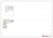
Hi Felipe. Everything is on Pavel's website (DIYaudio member ppy).
Just finished my dsc2,. I have a little noise issue in one channel, but I am going to sort that out.
Two things to comment.
1. There is apparently no connection from Amanero ground to ground before the isolator, meaning the ISO chip does not get power on its primary side. Easy rectified by a wire on the back side.
2. Why specify 5V at J1 when there is a 5V regulator onboard?
1. on previous gerber version there was an error on gnd connection on the header of the amanero. i fixed mine by scratching soldermask and the bridging the pin of the header to it.
the gerber version you can download today is fixed.
2. same question i have made to pavel... no real answer received. i am using with 5v to the BBG and 6v on the reclock and 7.5v on the output.
If at First You Don't Succeed, Try, Try Again
It's looking good with the second attempt at building one of Pavel's isolator/reclocker boards. I've mounted it on a BBB and have been running it as an HQP NAA with a DSD512 stream.
HQP works correctly, switching between 44.1KHz and 48KHz data so I must assume the oscillators and associated switching are working correctly and the Masterclock output is getting through the isolator to the BBB.
I've also checked DSD-on and Mute; both 3.3V when there's nothing playing and 0V when there is.
I can't connect check the data outputs from the reclocker as I don't have a dac board handy without a significant amount of dismantling of my DSC2 project, nor an oscilloscope until next week but it's all looking promising.
You could check whether a raw DSD data output indeed produces DSD data by filtering its output signal with some makeshift low-pass filter, a 1 kohm-10 nF first-order RC-filter for example, and then AC coupling it into an amplifier input using a capacitor of a few microfarads. If you hear music, then it is OK.
Don't turn up the volume too much, though, as ultrasonic residues might damage your tweeters at high volumes and the noise floor will probably be quite high anyway.
Don't turn up the volume too much, though, as ultrasonic residues might damage your tweeters at high volumes and the noise floor will probably be quite high anyway.
You could check whether a raw DSD data output indeed produces DSD data by filtering its output signal with some makeshift low-pass filter, a 1 kohm-10 nF first-order RC-filter for example, and then AC coupling it into an amplifier input using a capacitor of a few microfarads. If you hear music, then it is OK.
Don't turn up the volume too much, though, as ultrasonic residues might damage your tweeters at high volumes and the noise floor will probably be quite high anyway.
Yes, that occured to me too. I did build several simple No-DAC boards, like your suggestion, back along but I couldn't find one hanging around in a spares box, however, if I can find the parts it might be a cheap and cheerful way of checking...
I actualy had some success with my No-DACs and they were an early part of my getting on the DSD road. They sounded good and ultrasonic noise wasn't intrusive - main issue was with getting muting to work.
The my aim was not to prove that the distortion of ct7302 + dsc 2 is low as a traditional dac.
I am not in a position to verify this because now I have only a development environment with 10cm long I2S connection, with 10cm DSD connection and my oscillator is connected to an external pcb 10cm away from the CT7302.
In these conditions it is almost a miracle that something comes out.
I have only shown that the CT7302 in its best configuration with external reference oscillator at 24.576MHz and in SRC mode 2 works very well.
I have this comtrue board for years but never tried external MCK. Are there any chance to get the firmware and instructions for this modification?
Thanks
")
.
Last edited:
Hi DSC2 - Cronus folk
After a two week head scratching session I finally got the DSC2 - Cronus - Amanero setup working using the mcluxun interface board (Official GB for DSD DAC Signalyst DSCv2). Big thanks to Mcluxun. He provided an elegant way to get this hooked up. There is another board available on Oshpark but I did not try it as it may have been designed considering DSC1 board size where the connector was closer to the edge. The promised Cronus pdf manual is still not available.
Items to look out for if you try this:
1. New Cronus board has a 3-pin header to select between MCK + or -. CONNECT one of those options (usually +). Also select the appropriate speed on the jumpers which coincide with the crystal speed, ie 1:1 for 22MHz/25MHz or 1:2 for 45/49MHz or 1:4 for 98Mhz crystals.
2. Slave firmware works well so now just set the "configuration bits" for MCK/1. Anything else made foobar run 2x or 4x faster. Might sound interesting.
3. On mcluxun board: It is easy to get a solder bridge under the U.Fl connectors. Solder braid fixes that, luckily. The isolator chip is oriented as shown on the photos (not very clear) but can be worked out using a datasheet. CONNECT a 3.3V DC supply on the board (not connected on previous photos but mentioned in mcluxun post). Now your DSC is completely isolated from the PC. That is after all why you bought the Cronus.
Happy listening.
Success!
I have music from my DSC2 V2.5.2 - rather belatedly and it didn't help to be completely thrown off track by receiving a Cronus reclocker with the wrong regulator chip.
Anyway, with the replacement Cronus installed everything is working well and music is playing without any issues/problems - correct speed, no obvious noise and no loud bumps/pops. I can't comment on absolute sound quality yet as I'm listening through a cheap pair of computer speakers while I check everything out. All that remains to do is to properly connect the outputs to the chassis phono sockets and to screw the lid on. Here are a couple of pictures;


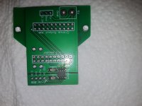
As it was commented on in the previous post, the Cronus connects to the DSC2 with a small bridging board that I designed - it just bridges between the headers of the two boards and has a simple isolator for the DSD-ON and MUTE signals from the Beaglebone.
I have music from my DSC2 V2.5.2 - rather belatedly and it didn't help to be completely thrown off track by receiving a Cronus reclocker with the wrong regulator chip.
Anyway, with the replacement Cronus installed everything is working well and music is playing without any issues/problems - correct speed, no obvious noise and no loud bumps/pops. I can't comment on absolute sound quality yet as I'm listening through a cheap pair of computer speakers while I check everything out. All that remains to do is to properly connect the outputs to the chassis phono sockets and to screw the lid on. Here are a couple of pictures;
As it was commented on in the previous post, the Cronus connects to the DSC2 with a small bridging board that I designed - it just bridges between the headers of the two boards and has a simple isolator for the DSD-ON and MUTE signals from the Beaglebone.
Attached is a picture of my PCB that connects Cronus to DSC2 by bridging the headers. It has a power connector for the 5V needed for the Cronus, and an isolator for DSD-ON and MUTE.
I use a small plug-in 3.3V regulator sub-board to power the clean side of the isolator but any convenient 3.3V supply could be used.
I have a couple of these boards spare if anyone would find one useful - PM me if you would like one.
I use a small plug-in 3.3V regulator sub-board to power the clean side of the isolator but any convenient 3.3V supply could be used.
I have a couple of these boards spare if anyone would find one useful - PM me if you would like one.
Attachments
Last edited:
very neat and clean work ! congrats
can I ask where do you get your enclosures done ?, it looks superb to me
pm sent nautiboy
Thanks for the comments.
Chassis was from China via a European ebay seller. Machining was by Schaeffer in Germany.
May listening bliss shine upon you ;-)
Thanks Jesper. I hope to find out how it performs in the main system over the weekend and will report back - I have high expectations based on my use of one of ppy's earlier DC boards.
Ray
I've been at home today so I left the DSC2 playing music all day into a headphone amp to start the 'burn-in' process. The HPA is nothing very special but an awful lot better than listening to the computer speakers and I did actually listen through my headphones for an hour or two; I like what I'm hearing so far and I'm excited about listening through the main system soon.
Raj, I won't be able to compare the DSC2 with an AK DAC in DSD mode as I don't have one.
Raj, I won't be able to compare the DSC2 with an AK DAC in DSD mode as I don't have one.
- Home
- Source & Line
- Digital Line Level
- Signalyst DSC1