I have been thinking about design a Si570 based low jitter audio clock board for a long time. At the beginning, I thought it would be part of the asynchronized FIFO project. But later on, I realized it could be a universal audio clock board supporting different kinds of digital audio applications, integrating with FIFO is just one of its features.
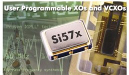
Si570 is one of the flagships of Silicon Labs low jitter programmable XOs. It’s based on DSPLL technology. Ham guys did a lot of research on it to improve their radio signal quality and found it comes with very good performance by comparing with other high-end low phase noise oscillator sources. The good thing is, with only one chip, it could generate low jitter clock at any frequency between 10-160Mhz, which can cover all the digital audio frequencies range, such as 11.2896 ….24.5760…33.8688...49.1520….98.304MHz….
From the specification, the time domain period jitter is 2ps RMS and 14ps PEAK-TO-PEAK, which sounds not that bad.
At the phase domain, although the close-in phase is not as good as CCHD957, but it’s already much better than most of the normal audio oscillators we can touch.
Here I have a comparison table,
CWX813 Si570 CCHD957
10Hz -60dB N/A -97dB
100Hz -90dB -112dB -126dB
1KHz -125dB -122dB -148dB
10KHz -140dB -132dB -162dB
100KHz -145dB -137dB -171dB
1Mhz N/A -144dB -170dB
10Mhz N/A -150dB N/A
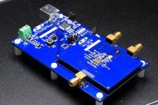
I’m having an original Si570 evaluation board, so I got chance tasting it on my FIFO platform before I really finish the clock board. During the real listening test, the sound of Si570 was quite impressed. It comes with much more details and crystal clear wide and deep 3D imaging. Actually I tested a whole bunch of clocks. Si570 beat all of them except CCHD957. It's better than what I expected. So, I decided giving the Si570 clock board a try.
Here I list both advantages and disadvantages of Si570 based clock board just for reference
Advantages:
1. Generating low jitter audio clock for multi-frequencies with one chip solution. Especially for some frequencies for which very hard to get good audio clocks.
2. Not that sensitive to the power supply.
3. To cover the full digital audio frequency range, the cost will be less than using CCHD957 or other low jitter oscillators.
4. Supporting almost all kinds of applications which need low jitter digital audio clocks such as CD players, SACD players,Network/HD players, DACs, USB interface, ASRCs,DSPs…...
5. Integrating with FIFO project seamlessly to switch between different Fs.
6. Very flexible and calibratble under the software support.
Disadvantages:
1. Close-in phase noise performance is not as good as CCHD957 or sc-cut oscillators.
2. Need software driver when switching frequency (not all the time).
3. 100mA power consumption which is a bit higher than normal oscillators.
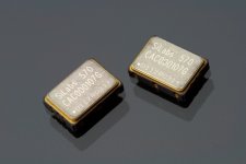
Below are pictures of Si570 and the evaluation board
Si570 is one of the flagships of Silicon Labs low jitter programmable XOs. It’s based on DSPLL technology. Ham guys did a lot of research on it to improve their radio signal quality and found it comes with very good performance by comparing with other high-end low phase noise oscillator sources. The good thing is, with only one chip, it could generate low jitter clock at any frequency between 10-160Mhz, which can cover all the digital audio frequencies range, such as 11.2896 ….24.5760…33.8688...49.1520….98.304MHz….
From the specification, the time domain period jitter is 2ps RMS and 14ps PEAK-TO-PEAK, which sounds not that bad.
At the phase domain, although the close-in phase is not as good as CCHD957, but it’s already much better than most of the normal audio oscillators we can touch.
Here I have a comparison table,
CWX813 Si570 CCHD957
10Hz -60dB N/A -97dB
100Hz -90dB -112dB -126dB
1KHz -125dB -122dB -148dB
10KHz -140dB -132dB -162dB
100KHz -145dB -137dB -171dB
1Mhz N/A -144dB -170dB
10Mhz N/A -150dB N/A
I’m having an original Si570 evaluation board, so I got chance tasting it on my FIFO platform before I really finish the clock board. During the real listening test, the sound of Si570 was quite impressed. It comes with much more details and crystal clear wide and deep 3D imaging. Actually I tested a whole bunch of clocks. Si570 beat all of them except CCHD957. It's better than what I expected. So, I decided giving the Si570 clock board a try.
Here I list both advantages and disadvantages of Si570 based clock board just for reference
Advantages:
1. Generating low jitter audio clock for multi-frequencies with one chip solution. Especially for some frequencies for which very hard to get good audio clocks.
2. Not that sensitive to the power supply.
3. To cover the full digital audio frequency range, the cost will be less than using CCHD957 or other low jitter oscillators.
4. Supporting almost all kinds of applications which need low jitter digital audio clocks such as CD players, SACD players,Network/HD players, DACs, USB interface, ASRCs,DSPs…...
5. Integrating with FIFO project seamlessly to switch between different Fs.
6. Very flexible and calibratble under the software support.
Disadvantages:
1. Close-in phase noise performance is not as good as CCHD957 or sc-cut oscillators.
2. Need software driver when switching frequency (not all the time).
3. 100mA power consumption which is a bit higher than normal oscillators.
Below are pictures of Si570 and the evaluation board
Attachments
Last edited:
Yeah, it is a favorite of HAM radio people.
I suspect you are thinking of a group buy, so I'll give my suggestions:
- Two board design: one for the clock and related power exposing the I2C interface, the other for the uP (and display, etc)
- Selectable I2C address for the clock board
If used with the FIFO kit, the clock can be tailored to match the input sample frequency and thus reduce the latency of having to fill up the fifo
To save repeat questions I have put together an index of (IMHO) the most interesting Si570 related posts by Ian in his FIFO R&D thread:
1. Post 881 - Initial testing of custom Si570 v1 board frequencies
2. Post 913 - ESS 9018 testing with sync mclk from Si570 - post includes selectable sets of frequencies for different DAC types and some discussion on next steps.
3. Post 929 - Additional comments & continuation of Post 913.
4. Post 1004 and Post 994 - Image of v2.0 pcb layout and new features in v2 design.
[I hope these links work for everyone, I have removed the page number and just included the post# in the url, which I think should result in diyA autoforwarding everyone based on their own number of posts/page setting in their user profile]
I think this set of data is quite pertinent to this thread also. I missed it in my earlier review of the FIFO thread. Perhaps this is just a slightly better formatted version of the table in Post #1 of this thread though.
.........Si570....... CCHD957
10- Hz N/A .........-97dB
100Hz -112dB ....-126dB
1-KHz -122dB ....-148dB
10KHz -132dB ....-162dB
100KHz -137dB ...-171dB
1-Mhz -144dB .....-170dB
10Mhz -150dB ......N/A
100Mhz N/A .........N/A
ahh I see where youre going with this, yes I would think so, the crystek numbers are all over the map, not predictable in a linear way wrt frequency. If I was to guess, I would presume its because they all use the same base crystal, but that there are harmonics from the mulitplier/amplifier that relate to higher noise at some frequencies.
It may not be that simple with the Si570 either, ie. itr may not be a linear progression from lower noise on lower Fs parts->higher noise at higher Fs parts, but logically thats what one would expect, that lower speed = lower power= lower noise. I guess in the case of the Si570 we have (at least) 6 possible factors that contribute to the noise of the part
1. the fundamental noise of the crystal itself
2. the noise/stability of the PLL
3. the noise and distortion of the internal multiplier/amplifier and its sidebands and where these harmonics are in relation to our chosen frequencies
4. the PSRR vs Fs of the amplifier
5. the PSRR vs Fs of the internal power supply?
6. the noise of the internal logic/control circuits (I understand its not really a factor in use here, because they can be disabled after frequency is set)
is that about right Ian?
Last edited:
thanks for correction.
120mhz=output frequency.
Thus could we optimistically expect better phase noise performance for 98.304mhz or lower?
Si570 is a programmable XO with output frequency range from 10-160Mhz (CMOS version) and resulution<1ppb. So they measured it at 120MHz is reasonable.
Normally lower frequency is better for phase noise performance. Especially for SC cut crystals. That's why it's easy find a very good 10MHz low jitter clock, but very hard to find 90.xxx and 98.xxx MHz ones.
Regards,
Ian
Last edited:
ahh I see where youre going with this, yes I would think so, the crystek numbers are all over the map, not predictable in a linear way wrt frequency. If I was to guess, I would presume its because they all use the same base crystal, but that there are harmonics from the mulitplier/amplifier that relate to higher noise at some frequencies.
It may not be that simple with the Si570 either, ie. itr may not be a linear progression from lower noise on lower Fs parts->higher noise at higher Fs parts, but logically thats what one would expect, that lower speed = lower power= lower noise. I guess in the case of the Si570 we have (at least) 6 possible factors that contribute to the noise of the part
1. the fundamental noise of the crystal itself
2. the noise/stability of the PLL
3. the noise and distortion of the internal multiplier/amplifier and its sidebands and where these harmonics are in relation to our chosen frequencies
4. the PSRR vs Fs of the amplifier
5. the PSRR vs Fs of the internal power supply?
6. the noise of the internal logic/control circuits (I understand its not really a factor in use here, because they can be disabled after frequency is set)
is that about right Ian?
Si570 is a XO, while Si571 is a VCXO. It seems that 570 has better phase noise performance than Si571.
Here is the possible internal picture of Si570, hope you can get some idea from it.
Ian
Attachments
Thanks Ian! yes i'd seen that, the factors I mention above still hold with the 570 dont they?
I wonder if its possible to find a higher performance version of the Si5351 and use it with a very high quality SC cut fundamental crystal for even higher DSPLL performance? dont get me wrong, i'm keen as mustard on the current Si570 design. I mentioned this possibility much earlier in the fifo thread before you had verified that the 570 works so well in a properly focused design. provided this GB gets off the ground, doing something like this might be something for the next version? hehe
gotta love my chronic upgraditus, i'm already looking for ways to spend money on upgrades for parts I dont even have yet
Thanks Ian! yes i'd seen that, the factors I mention above still hold with the 570 dont they?
I wonder if its possible to find a higher performance version of the Si5351 and use it with a very high quality SC cut fundamental crystal for even higher DSPLL performance? dont get me wrong, i'm keen as mustard on the current Si570 design. I mentioned this possibility much earlier in the fifo thread before you had verified that the 570 works so well in a properly focused design. provided this GB gets off the ground, doing something like this might be something for the next version? hehe
gotta love my chronic upgraditus, i'm already looking for ways to spend money on upgrades for parts I dont even have yet
Had similar Si5317 evaluated. Not as good as 570. Havn't try 5351 yet, it may be good working with a 10MHz SC cut crystals, will look for some details.
Ian
Reading the post on the SC-crystal oven from Andrea made me check the specifications of my SI570 boards I purchased 1-2 years ago. I have a SI570BBC and a SI570CAC what version have you tested and what version will you put in the futur SI570 board in GB IV?
I saw in the datasheet that a 7ppm Temperature Stability (20ppm total) version SI570?C? should exist. The Si570 BBC000141DG LVDS (280 MHz Max) seems the affordable one vs specs ...
I saw in the datasheet that a 7ppm Temperature Stability (20ppm total) version SI570?C? should exist. The Si570 BBC000141DG LVDS (280 MHz Max) seems the affordable one vs specs ...
- Status
- This old topic is closed. If you want to reopen this topic, contact a moderator using the "Report Post" button.
- Home
- Source & Line
- Digital Line Level
- Si570 based 2ps RMS low jitter universal audio clock project