Yes, +1. Thanks for that Demian - very interesting! So, my next iteration should remove the XO reg from the McDualXO board and power the oscillators separately. I'll report back.
I'll report back.
I took the plunge snapped off the XO reg installed some header pins and tried a variety of decent reg boards with very little perceived difference. I then tried a lifepo directly wired to the header pins and had to swap it back and forth a few times but there was definitely something 'good' there that hadn't been with the regs...a little more definition perhaps, space...
Probably some expectation bias in there too but I was watching out for that so make of it what you will!
Just a tip that might be useful for anyone that's going to give this a go, don't let your heart skip a beat...or take an extra one...when the green LED (near the clocks) doesn't light when you power up the XOs...it's not supposed to. I powered the clocks first before powering up the board and thought I'd screwed up.
Also, best to use a couple of lifepos in parallel (as I think Ian mentioned elsewhere in this thread) as I had occasional dropouts at DSD and higher frequency tracks.
It's great to have the facility to be able to try this sort of thing - a big thanks to Ian for designing his boards like this!
Another couple of builds using Ian's FIFO....
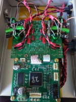
I haven't seen a lot of setups using Ian's FIFO-based gear posted recently, so I thought I'd put my latest up here.
I just got both of my Twisted Pear Buffalo-III Pro setups fully running. One is the ES9038 version of course into their Mercury. The other is the ES9028 version, which I've run with 2 different I/V stages. One is a 'truncated' IVY using just 1 OPA1632 per channel in the configuration Joe Rasmussen published a couple of years ago. The other is their Legato. The ES9038 won my head, the ES9028 with the Legato won my heart.
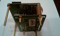
The setup is fed from a modified RPi->Ian IsolatorPi->allo.com Kali->Ian RPi I2S adapter. This goes into an original FIFO->isolator board->Dual Clock Board. A large part of why I included the FIFO setup is to provide a clock domain I can use to configure the Buff-III Pros to run in Sync mode, which some have tried and liked.
Power is a bit different than the typical setup:
- The RPi has been modified with an ldovr.com 3-rail mezzanine to provide the 1.8V, 3.3V, and 5V needed by the Pi and allow me to remove the onboard DC-DC converter. It is fed from a 6V Stammheim dual 3||LT3045 board which is fed from 2 Uptone Audio LPS-1.2 Ultracap supplies, which provide totally off-the grid power.
- The IsolatorPi and Kali each are powered by a 3rd & 4th Uptone Ultracap supply, LPS-1's here.
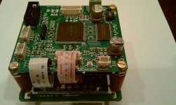
- The FIFO & DAC boards are powered by an array of 4 normal-ish power supplies with each sporting an oversized toroid, good fast-recovery diodes, and a 47000uF Jensen 4-pole cap. The FIFO & isolator input side are fed via one of Ian's TPS7A4700 boards set to 6V. The isolator output side and Dual Clock board are fed via an Acko AKR75 ADM715x-based regulator set to 5V. The Buffalos get their 5V VD from a Belleson SPZ 8A regulator mounted right on the DAC board, with the on-board regulators split between 2 TP Trident SR's for the 1.3V VDD & 3.3V DVCC and 3 LT3042-based boards OPC had made when he was still active here, 2 for the AVCC L&R and 1 for the VDD_XO.
The FIFO and Dual Clock board get their own supply with the DAC board using the 3rd. The 4th is there for later experiments with separately powering the AVCC rail.
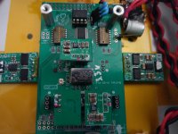
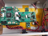
- The I/V stages have a +- supply similar to the ones for the DAC and digital front end, but with an appropriately-sized R-Core transformer instead of a toriod. Each board has a set of 4 discrete regulators providing +-15V to each channel of the board... the 'truncated' IVY is fed from small shunt regulators of a design from Ric Schultz of EVS (sorta like a simplified Salas), the Legato has 4 of the new discrete Dexa regulators, and the Mercury has 4 of the discrete Sparkos regulators. Right now I'm running them in single-ended mode, but they'll get moved over to balanced as I finalize their configurations.
I worked hard to keep the signal runs short and direct along with short power supply runs and closely-placed regulators, drawing a lot of inspiration from Twisted Pear's DAC board design.
The great sounds I'm getting from each configuration are due to a lot of outstanding building blocks... Twisted Pear, Ian, OPC, Ric Schultz, Acko, Dexa, Sparkos, Allo.com, ldovr.com. BUT by count, Ian has more pieces in this setup than anyone else. THANKS for the great digital audio components that make DIY'ing gear like this possible... and sounding great!
Greg in Mississippi
I haven't seen a lot of setups using Ian's FIFO-based gear posted recently, so I thought I'd put my latest up here.
I just got both of my Twisted Pear Buffalo-III Pro setups fully running. One is the ES9038 version of course into their Mercury. The other is the ES9028 version, which I've run with 2 different I/V stages. One is a 'truncated' IVY using just 1 OPA1632 per channel in the configuration Joe Rasmussen published a couple of years ago. The other is their Legato. The ES9038 won my head, the ES9028 with the Legato won my heart.
The setup is fed from a modified RPi->Ian IsolatorPi->allo.com Kali->Ian RPi I2S adapter. This goes into an original FIFO->isolator board->Dual Clock Board. A large part of why I included the FIFO setup is to provide a clock domain I can use to configure the Buff-III Pros to run in Sync mode, which some have tried and liked.
Power is a bit different than the typical setup:
- The RPi has been modified with an ldovr.com 3-rail mezzanine to provide the 1.8V, 3.3V, and 5V needed by the Pi and allow me to remove the onboard DC-DC converter. It is fed from a 6V Stammheim dual 3||LT3045 board which is fed from 2 Uptone Audio LPS-1.2 Ultracap supplies, which provide totally off-the grid power.
- The IsolatorPi and Kali each are powered by a 3rd & 4th Uptone Ultracap supply, LPS-1's here.
- The FIFO & DAC boards are powered by an array of 4 normal-ish power supplies with each sporting an oversized toroid, good fast-recovery diodes, and a 47000uF Jensen 4-pole cap. The FIFO & isolator input side are fed via one of Ian's TPS7A4700 boards set to 6V. The isolator output side and Dual Clock board are fed via an Acko AKR75 ADM715x-based regulator set to 5V. The Buffalos get their 5V VD from a Belleson SPZ 8A regulator mounted right on the DAC board, with the on-board regulators split between 2 TP Trident SR's for the 1.3V VDD & 3.3V DVCC and 3 LT3042-based boards OPC had made when he was still active here, 2 for the AVCC L&R and 1 for the VDD_XO.
The FIFO and Dual Clock board get their own supply with the DAC board using the 3rd. The 4th is there for later experiments with separately powering the AVCC rail.
- The I/V stages have a +- supply similar to the ones for the DAC and digital front end, but with an appropriately-sized R-Core transformer instead of a toriod. Each board has a set of 4 discrete regulators providing +-15V to each channel of the board... the 'truncated' IVY is fed from small shunt regulators of a design from Ric Schultz of EVS (sorta like a simplified Salas), the Legato has 4 of the new discrete Dexa regulators, and the Mercury has 4 of the discrete Sparkos regulators. Right now I'm running them in single-ended mode, but they'll get moved over to balanced as I finalize their configurations.
I worked hard to keep the signal runs short and direct along with short power supply runs and closely-placed regulators, drawing a lot of inspiration from Twisted Pear's DAC board design.
The great sounds I'm getting from each configuration are due to a lot of outstanding building blocks... Twisted Pear, Ian, OPC, Ric Schultz, Acko, Dexa, Sparkos, Allo.com, ldovr.com. BUT by count, Ian has more pieces in this setup than anyone else. THANKS for the great digital audio components that make DIY'ing gear like this possible... and sounding great!
Greg in Mississippi
Attachments
@ Greg,
Looks very nice indeed!
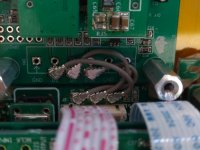
Where did you find those short u.fl cables?
How did you compare the your low noise regs with Twisted Pear ones?
Did you buy the bare I/V PCB from Twisted Pear and assembled it by yourself?
Regards,
Ian
Looks very nice indeed!
Where did you find those short u.fl cables?
How did you compare the your low noise regs with Twisted Pear ones?
Did you buy the bare I/V PCB from Twisted Pear and assembled it by yourself?
Regards,
Ian
@ Greg,
Where did you find those short u.fl cables?
I think they're these Ian: http://uk.farnell.com/hirose-hrs/u-fl-2lp-088k1t-a-50/cable-u-fl-u-fl-50mm-50ohm/dp/1688071
Lovely work Greg - always like reading your posts!
@iancanada, @Crom, thanks for the kind comments.
Crom, you hit the nail on the head with the u.fl cables... the ones I ordered were these:
U.FL-2LP-066J1-A-(35) Hirose Electric Co Ltd | Cable Assemblies | DigiKey
Same line from Hirose as you posted. My ultimate intention is to hard-wire one end (likely the inputs to the DAC and FIFO)... does anyone know if the carefully engineered & implemented u.fl connections are better than if I carefully cut and prepare the u.fl coax cable and soldered them in? I've done this before and have a pretty good process and technique, but I'm not sure if it is actually better.
Ian, I did assemble the 'truncated' IVY and the Legato that I'm using. Neither has the single-ended outputs populated as they'll ultimately be used in balanced setups. AND I used some alternative parts... PRP resistors, PPS SMD film caps, and dug into my stock of Black Gates for local power supply caps.
The Mercury is of course only sold assembled, I did use Nichicon Muse for the local power supply caps and Amtrans polyprops for the filters (thanks Barrows for the suggestion!).
Still a bit of tweaking and adjusting to do, but all are working swimmingly!
Greg in Mississippi
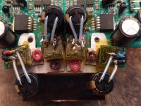
P.S. Another picture, showing the Sparkos Lab regulators on the Mercury. I've always liked very short paths from my final regulation stages to the powered stages... this is as close as I can get them without some hackery, of course, which I'm not above, but didn't want to descend there for the first implementation.
Greg in MIssissippi
Greg in MIssissippi
Attachments
does anyone know if the carefully engineered & implemented u.fl connections are better than if I carefully cut and prepare the u.fl coax cable and soldered them in? I've done this before and have a pretty good process and technique, but I'm not sure if it is actually better.
Greg,
In theory (got to get the disclaimer in 😀).... the connector should be better than a soldered connection. In RF geometry is king. (oh plus material properties, but that's another can of worms) Each geometry mismatch creates reflections, these are your enemy in RF design, it pays dividends in signal integrity to keep your signal paths as contiguous and short as possible. Those who are curious:
Return loss - Wikipedia
At high frequencies the UFL should maintain a more coherent impedance than the soldered connection when traversing boundaries between PCB and cable.
Simon,
The places where I've used soldered-in u.fl cables so far has been where one side does not have u.fl connectors, but the other side does, such as at the I2S input to my Soekris DAM1021 DAC boards. In these cases, I strongly suspect the soldered connection (rather than using other types of connectors for an I2S signal) is better.
When we get to the world of u.fl versus soldered, this is where I wonder if in practice, theory is overcome by reality. Is one pair of soldered connections (cable end signal and ground) better than another pair of soldered connections (u.fl to board pads) AND an appropriate geometry non-soldered connection (u.fl male to u.fl female)?
If it is better at first, how about after a year on the metal to metal connections?
How about after 10 disconnects/reconnects?
Or even just a time of stressing the connector while moving the boards around?
OR if the u.fl-to-u.fl connection is better, is that connection still better if a soldered connection on one end could allow you to halve the cable length, as in my picture a few posts back?
I don't know the answers to these questions. I hope someone can offer some insight. Simon, I appreciate your response, assessment, and link!
Greg in Mississippi
You may well be right about soldered connections being better than say one of those little 0.1" spring crimp terminations often used Greg.
As to cable length, for a given frequency band a correctly specified coaxial cable is a well defined geometry and impedance. In theory the only thing that you lose is a teeny bit of level, typically 1dB every 3 meters or so. I can't see the difference between 50mm and 100mm cables of the same type making any difference whatsoever.
UFL connectors are designed for point to point internal connections that are fit and forget. They are very reliable in that application from my experience (RF signal handling) but they are rated for a very low number of make-break cycles, typically around 30. Its the wrong connector if you are going to constantly change stuff about, but I'm sure Ian is aware of that. Forgive me but I am betting you aren't his typical customer Greg 😀
Last edited:
@ simon dart
Agree with you on the " low number of make-break cycles" 🙂.
Based on my experience, I can do it more than 100 time without having problem. I have been using I-PEX RF sockets and connectors for long time. I'm very happy with the quality.
Regards,
Ian
Agree with you on the " low number of make-break cycles" 🙂.
Based on my experience, I can do it more than 100 time without having problem. I have been using I-PEX RF sockets and connectors for long time. I'm very happy with the quality.
Regards,
Ian
I have built the DAC(pcm1794) which integrated FIFO to buff input data stream 10 years ago. The solution is based on FPGA.
FPGA is play as DSP for interpolation up to 32x (48KHZ sample rate) and FIFO to buff the data. Input data is driven by the clock recovered from DIR. Recovered clock is write clock for FIFO. Read clock is generated by a DDS chip, which is configured by FPGA. FPGA run DPLL algorithm to cancel the jitter from writing clock and drive DDS. The DPLL bandwidth is lower than 10HZ.
I measured phase noise with 1KHZ sine wave output by spectrum analyzer(RBW 1HZ). Obviously, The phase noise at 1KHZ+/-100HZ improved a lot.
I think the key is NOT FIFO. FIFO is used to buffer the data. The key is jitter attenuater. Include the DPLL algorithm and VCO(Could be VCXO, PLL chip, DDS, etc...)
Regards,
Laurel
FifoPi, the next generation all in one I2S/DSD/DoP FIFO for Raspberry Pi
To achieve higher performance and better sound quality, I finally decided to design my own FIFO for raspberry Pi based on my third generation FIFO technology.
I'd like FifoPi to have the following features and specifications:
1. Up to 768KHz full range I2S support;
2. DSD64,128,256,512,1024;
3. built-in 768KHz DoP decoder to enable RaspberryPi native DSD play back up to DSD256;
4. Isolator board will be included;
5. Clock board (isolated) will also be integrated, works with interchangeable XOs through standard sockets or adapters;
6. Supports full rang of XO frequencies from 11.2894 to 98.3040MHz;
7. Has two DC inputs for both isolated clean power and RaspberryPi power;
8. Has an additional non-isolated GPIO connector to make DAC controller working in isolated mode;
9. Works with good 5V linear power through on-board low noise LDO or pure direct 3.3V power from ulatr-capacitor or LifePO4 battery power supply;
10 Works with all RPi DAC HAT and external high-end DAC at synchronized master clock mode to remove jitter;
11. Optional external display panel with adjustable delay time;
12. DIY friendly with options and flexibility.
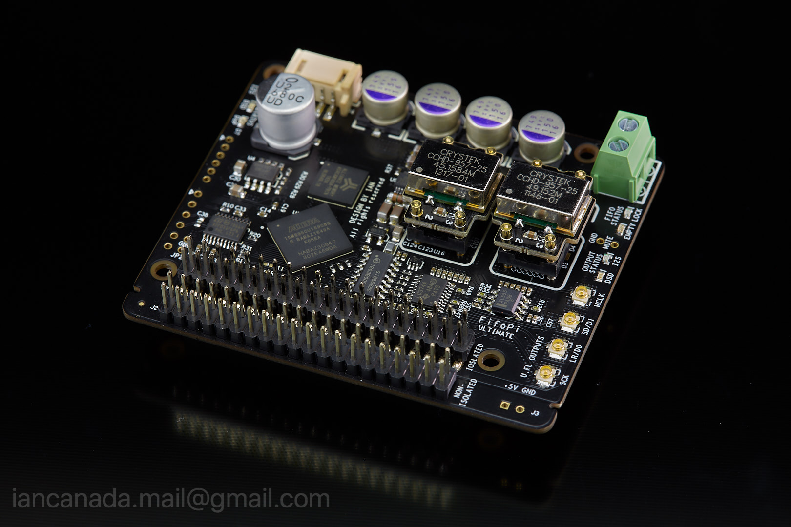
FifoPi_1 by Ian, on Flickr
Ian
To achieve higher performance and better sound quality, I finally decided to design my own FIFO for raspberry Pi based on my third generation FIFO technology.
I'd like FifoPi to have the following features and specifications:
1. Up to 768KHz full range I2S support;
2. DSD64,128,256,512,1024;
3. built-in 768KHz DoP decoder to enable RaspberryPi native DSD play back up to DSD256;
4. Isolator board will be included;
5. Clock board (isolated) will also be integrated, works with interchangeable XOs through standard sockets or adapters;
6. Supports full rang of XO frequencies from 11.2894 to 98.3040MHz;
7. Has two DC inputs for both isolated clean power and RaspberryPi power;
8. Has an additional non-isolated GPIO connector to make DAC controller working in isolated mode;
9. Works with good 5V linear power through on-board low noise LDO or pure direct 3.3V power from ulatr-capacitor or LifePO4 battery power supply;
10 Works with all RPi DAC HAT and external high-end DAC at synchronized master clock mode to remove jitter;
11. Optional external display panel with adjustable delay time;
12. DIY friendly with options and flexibility.
FifoPi_1 by Ian, on Flickr
Ian
Last edited:
FifoPi and ES9038Q2M DAC HAT
FifoPi makes ES9038Q2M DAC HAT working at pure sync clock mode. The MCLK u.fl cable is the only cable that needs to be connected for sound quality. Anything else will be plug and play.
ESS controller can be connected to the non-isolated GPIO of the FifoPi. I'm highly rerecorded doing it this way. With the FifoPi on-board isolator, ESS controller will be 100% isolated from ES9038Q2M DAC in this case. The processor of the controller will never have any galvanic impact to the DAC.
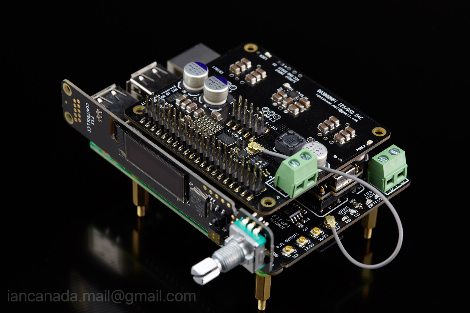
FifoPi_3 by Ian, on Flickr
Ian
FifoPi makes ES9038Q2M DAC HAT working at pure sync clock mode. The MCLK u.fl cable is the only cable that needs to be connected for sound quality. Anything else will be plug and play.
ESS controller can be connected to the non-isolated GPIO of the FifoPi. I'm highly rerecorded doing it this way. With the FifoPi on-board isolator, ESS controller will be 100% isolated from ES9038Q2M DAC in this case. The processor of the controller will never have any galvanic impact to the DAC.
FifoPi_3 by Ian, on Flickr
Ian
Attachments
That looks very nice
Thanks BryceJ for your interest. That will be discussed in the GB thread. To follow DiyAudio rules, I'll keep this thread focused on R&D, principle and experience sharing🙂.
Regards,
Ian
Last edited:
amazing! all your goodies roll into one credit card size board.
what low noise ldo you used? what is the size of fifo?
only one master clock output for dac? does it
does it has second master clock output for beaglebone black and amanero usb in slave clock control mode like mcfifo? bbb and amanero can do dsd512 output, adaptor pcb board can be make so we are not restricted to just rpi
- Home
- Source & Line
- Digital Line Level
- Asynchronous I2S FIFO project, an ultimate weapon to fight the jitter